Dispensing system with vacuum-filled metering chamber

a technology of vacuum-filled metering and dispensing system, which is applied in the field of single-serve beverage brewers, can solve the problems of relatively complex and expensive systems, and problems such as sealing problems

Inactive Publication Date: 2006-08-10
KEURIG INCORPORATED
View PDF33 Cites 100 Cited by
  • Summary
  • Abstract
  • Description
  • Claims
  • Application Information

AI Technical Summary

Problems solved by technology

Such systems are relatively complex and expensive, and are prone to developing sealing problems due to a build up of mineral deposits at critical interfaces.

Method used


Image

  • Dispensing system with vacuum-filled metering chamber
  • Dispensing system with vacuum-filled metering chamber

Examples


Embodiment Construction

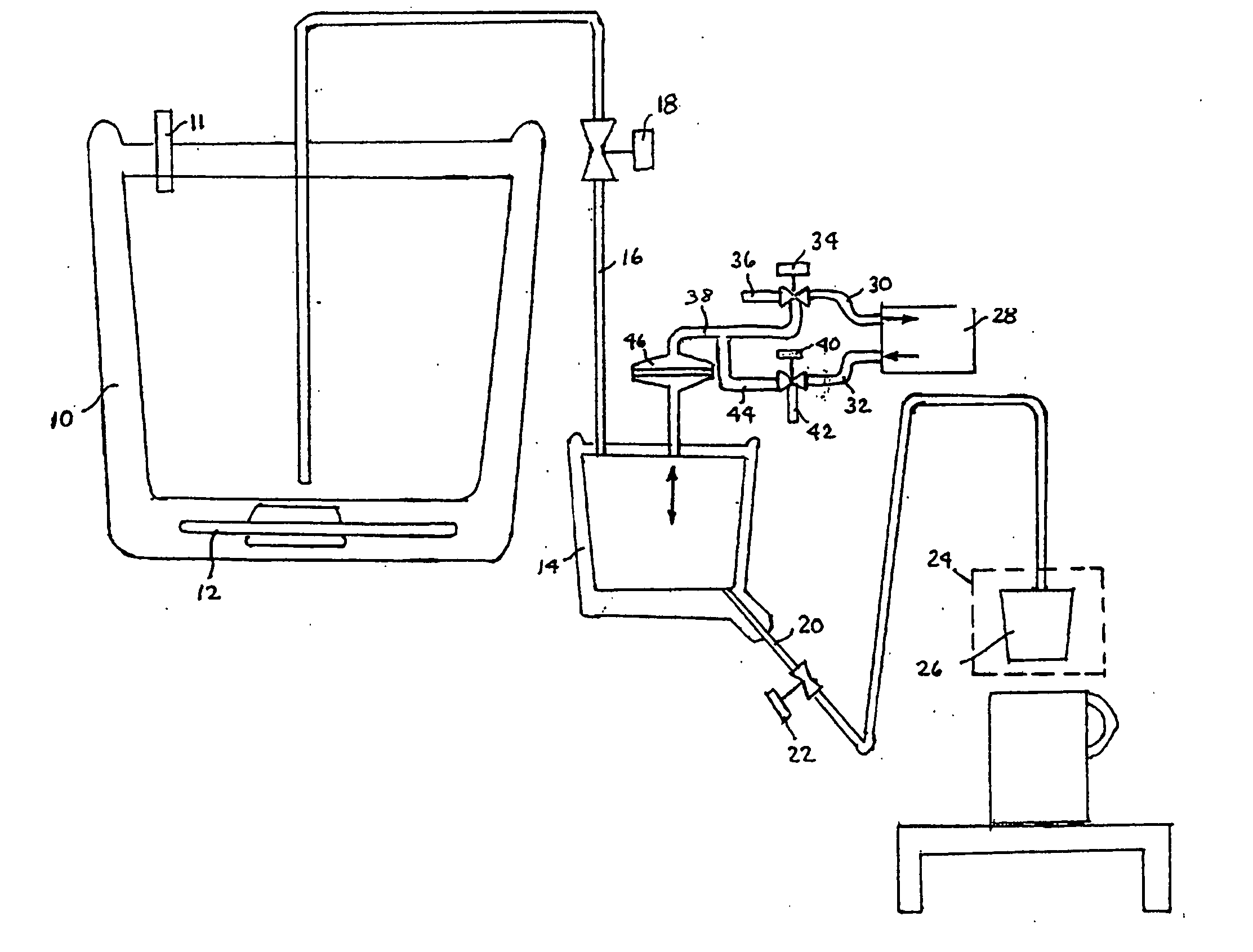
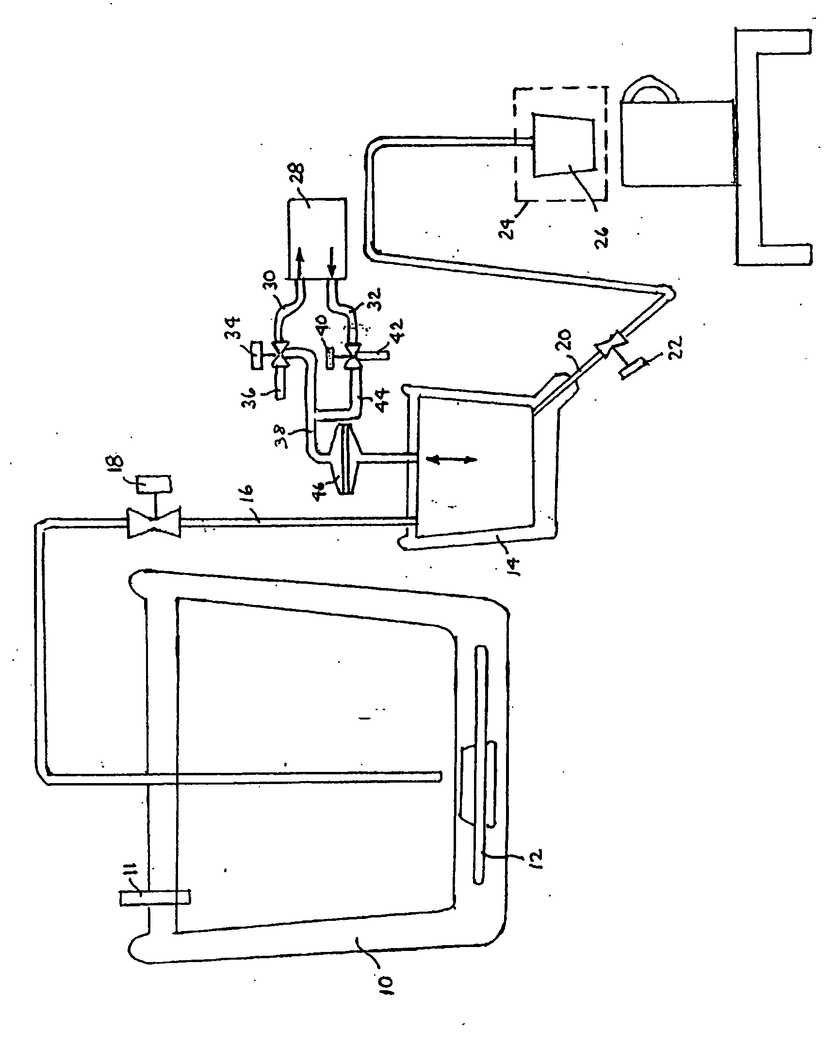
[0010] With reference to the accompanying drawing, a storage tank 10 contains a supply of water heated to an appropriate elevated temperature by a heater 12. The storage tank is vented to atmosphere at 11.

[0011] A metering chamber 14 is connected to the storage tank 10 by a supply conduit 16 which includes a first valve 18. The metering chamber 14 is also connected via a delivery conduit 20 and a second valve 22 to a brew chamber 24 adapted to receive a single serve beverage filter cartridge 26 of the type described, for example, in U.S. Pat. No. 5,840,189 (Sylvan et al.) and U.S. Pat. No. 5,325,765 (Sylvan et al.).

[0012] An air pump 28 has suction and discharge conduits 30, 32. A third valve 34 is adjustable to alternately connect suction conduit 30 to atmosphere via a vent 36 or to a conduit 38 communicating with the metering chamber 14. A fourth valve 40 is similarly adjustable to alternately connect discharge conduit 32 to atmosphere via a vent 42 or to a branch conduit 44 lea...


PUM


Abstract

A system for dispensing a metered volume of heated water from the storage tank to the brew chamber of a single serve beverage brewer comprises a metering chamber, a supply conduit connecting the storage tank to the metering chamber, and a delivery conduit connecting the metering chamber to the brew chamber. An air pump coacts with associated valves to alternately withdraw heated water from the storage tank into the metering chamber via the supply conduit, and to expel heated water from the metering chamber via the delivery conduit to the brew chamber.

Description

CROSS REFERENCE TO RELATED APPLICATIONS [0001] This application is a continuation application of prior U.S. application Ser. No. 10 / 790,533, filed Mar. 1, 2004.BACKGROUND OF THE INVENTION [0002] 1. Field of the Invention [0003] This invention relates generally to single serve beverage brewers, and is concerned in particular with an improved system for repeatedly dispensing the metered amounts of heated water required to effect successive brew cycles. [0004] 2. Description of the Prior Art [0005] Known water dispensing systems for single serve beverage dispensers commonly employ buoyant and / or mechanically activated metering components. Such systems are relatively complex and expensive, and are prone to developing sealing problems due to a build up of mineral deposits at critical interfaces. [0006] The objective of the present invention is to provide an improved air-activated system that avoids or at least significantly minimizes the above-mentioned shortcomings. SUMMARY OF THE INVEN...

Claims


Application Information

Patent Timeline
Patent Type & Authority Applications(United States)
IPC IPC(8): A47J31/00A47J31/46B67D7/08
CPCA47J31/46A47J31/469
Inventor TAYLOR, JON
Owner KEURIG INCORPORATED
Why Eureka
Try Eureka