Supercharged internal combustion engine

a supercharged, internal combustion engine technology, applied in combustion engines, non-positive displacement pumps, jet pumps, etc., can solve the problems of engine-driven superchargers with non-positive displacement compressors, small displacement ice often fails to provide satisfactory power, and only about one tenth of vehicle operating time, etc., to achieve good fuel economy, improve ice performance, and accelerate the effect of sufficien

Inactive Publication Date: 2006-07-18
VETROVEC JAN
View PDF19 Cites 56 Cited by
  • Summary
  • Abstract
  • Description
  • Claims
  • Application Information

AI Technical Summary

Benefits of technology

[0021]One of the central concepts of the supercharged ICE system according to the present invention applied to automotive vehicle is the recognition that under typical driving conditions the periods of high-power demand are relatively short and occur on the average only about 10% of the vehicle operating time. This means that a supercharger can be designed to operate in an intermittent mode, namely supercharging the ICE for about 10% of the vehicle operating time as demanded by vehicle driving conditions. This leaves on the average about 90% of the vehicle operating time available for recharging the supercharger.
[0032]It is still further object of the invention to provide a supercharger that can be used with hybrid vehicles to boost the power of the ICE and thus giving the hybrid vehicle more power to accelerate and ascend grade.

Problems solved by technology

However, under high torque conditions such as acceleration and grade ascent, small displacement ICE's often fail to provide satisfactory power.
Yet, the conditions demanding high torque generally represent only about one tenth of a vehicle operating time.
Engine-driven superchargers with nonpositive displacement compressors (i.e., turbine-type) were developed (as disclosed, for example, by Hall-Brown in U.S. Pat. No. 1,645,178) but did not provide adequate flow at low engine speeds associated with high torque conditions.
Compression in a supercharger heats up the intake air, thereby reducing its density and adversely impacting ICE performance.
These pumps are expensive since they use precision machined and accurately aligned rotor components.
Pump rotors spin at high speeds, typically in the range of 5,000 to 20,000 revolutions per minute (rpm), which leads to vibrations and wear.
Abrasion and wear gradually increase the precision clearances between mating rotor components which results in reduced supercharger performance.
Another limitation of engine-driven superchargers is the low volumetric output at low engine speeds.
This can be remedied by a variable speed drive, but only at a significant increase in complexity and cost.
Engine-driven superchargers also occupy a relatively large volume which complicates their integration into engine frame.
While being more space efficient, integral supercharger obstructs other ICE components and impedes ICE serviceability.
Engine-driven supercharger requires significant ICE power to operate and this power must be supplied at the least opportune moment, namely during high demand on ICE output, thus reducing ICE output power available for propulsion.
This often requires a complex control system.
However, turbochargers must run at very high rotational speeds (typically on the order of 20,000 to 100,000 rpm) and use sophisticated engineered materials to withstand the high temperatures of ICE exhaust, both of which requires rather costly construction.
Another disadvantage of turbochargers is a relatively long response time lag cased by the turbine inertia.
Furthermore, the nature of the exhaust gas flow and the turbine drive arrangement causes the supercharging flow to increase exponentially with engine rpm.
This results in relatively inadequate boost pressures at low engine speeds and excessive boost pressures at relatively high engine speed.
The latter is usually mitigated by control arrangements for reducing or limiting the output flow (e.g., using flow bypassing), but it results in a more complex design.
However, these ejectors do not pump ICE intake air, do not increase the ICE intake air pressure, and do not supercharge the ICE.
Therefore, the resulting compression ratio is very low albeit sufficient for EGR purposes.
Furthermore, these fluid pumps do not increase the ICE intake air pressure and do not supercharge the ICE.
As a result these jet pumps are inefficient, have a low compression ratio and deliver a warm charge to ICE combustion chamber.
Increasing the throughput of such jet pump requires increasing the quantity of ingested exhaust gas, which ultimately leads to increased charge temperature and limits the ICE output.
However, compressed air is not used for supercharging during normal ICE operation.
In addition, much of the potential (pressure) energy available in compressed air is wasted since the compressed air pressure is be reduced to near ambient intake pressure without performing any useful work.
Moreover, Moyer does not show how the air storage tank could be replenished by a compressor driven either by the ICE or an electric motor.
In summary, the prior art does not teach an ICE supercharging system that is effective at the conditions of high torque and low engine speed, has a fast response, is simple, economical, can be retrofitted onto existing ICE, does not dilute engine charge with exhaust gases, and does not rob engine of power during high power demand.
Furthermore, the prior art does not teach an ICE supercharged by an ejector pump driven by high-pressure air.
In addition, the prior art does not teach an ICE supercharged by an ejector pump with a supersonic driving nozzle.

Method used


Image

  • Supercharged internal combustion engine
  • Supercharged internal combustion engine
  • Supercharged internal combustion engine

Examples


example 1

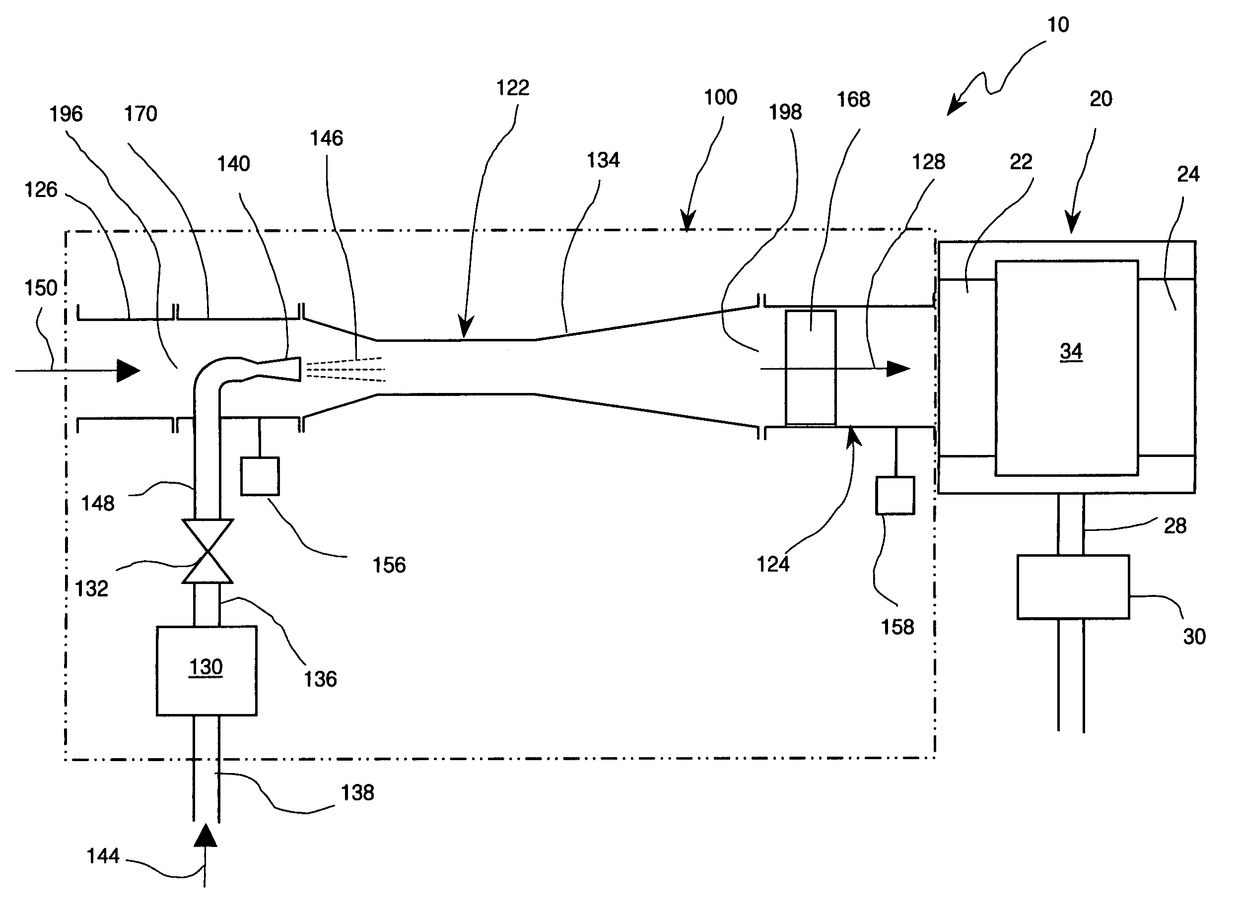
[0058]Consider a 4-cycle ICE with a 2 liter displacement. When operating at 1200 rpm the engine displaces 20 liters per second. Assume that under naturally aspirated conditions, the intake passage pressure is about 540 Torr (about 21.25 inches Hg), which translates to an intake air flow of about 14 standard liters per second. When equipped with the supercharger assembly 100, the ICE can be supercharged and the pressure in the intake passage 22 can be increased to 680 Torr (about 27 inches Hg) by flowing approximately 10 standard liters per second of air through the driving nozzle 140 of the ejector pump 122. This would theoretically boost the ICE output by about 25%.

[0059]As noted above, operation of the ejector pump 122 is controlled by regulating the flow through the nozzle 140, which in turn is regulated by the setting of the pressure regulator 130 (FIG. 4). One disadvantage of this approach is that the pressure regulator 130 causes a pressure drop (typically about 30 psi) in the...

example 2

[0065]Using the ICE and supercharger parameters from Example 1 with high-pressure air flow of 10 standard liters per second, the ejector pump consumes 100 standard liters in a 10 second supercharging event. Assuming that supercharging is necessary (on the average) about 10% of the vehicle operating time, the compressor has (on the average) about 100 seconds to replenish the high-pressure air in the air tank. Thus, the average flow rate through the compressor is 1 standard liter per second (about 2.3 cubic feet per minute). A suitable piston type compressor delivering high-pressure air at this flow rate would weigh about 7 kilograms (15 lbs), have a volume of about 5 liters (324 cubic inches) and require about 1 horsepower to operate. As already noted, during a supercharging event the ICE system power output would increase by about 25%.

[0066]Referring now to FIG. 9, there is shown a supercharger assembly 100″ in accordance with a second variant to the supercharger assembly 100 of the...


PUM


Abstract

A supercharged internal combustion engine system wherein the supercharger assembly includes an ejector pump driven by high-pressure air for pumping intake air into engine combustion chamber. Included are means for sensing engine power demand and controlling the supercharging action. A compressor and an air tank for providing high-pressure air for driving the ejector pump are also disclosed. During periods of natural aspiration the ejector pump can be by-passed to reduce flow impedance. The ejector pump can use a driving nozzle with a fixed throat or a variable throat, or a lobed nozzle. Effective supercharging is achieved even at low engine speeds. One of the objects of the invention is to obtain more power from small displacement ICE and thus providing automotive vehicles with sufficient acceleration in addition to good fuel economy.

Description

CROSS-REFERENCE TO RELATED APPLICATIONS[0001]Not ApplicableFEDERALLY SPONSORED RESEARCH[0002]Not ApplicableSEQUENCE LISTING OR PROGRAM[0003]Not ApplicableFIELD OF THE INVENTION[0004]The present invention relates to a supercharged internal combustion engine where engine intake air is pumped by an ejector pump operated by high-pressure air to boost engine output during increased power demand conditions.BACKGROUND OF THE INVENTION[0005]Overview: The current emphasis on fuel economy in the design of power plants for automotive application motivates the efforts to improve the performance of internal combustion engines (ICE) with relatively small displacement. It is well known that automotive vehicles with small displacement engines enjoy moderate fuel usage. However, under high torque conditions such as acceleration and grade ascent, small displacement ICE's often fail to provide satisfactory power. Yet, the conditions demanding high torque generally represent only about one tenth of a v...

Claims


Application Information

Patent Timeline
Patent Type & Authority Patents(United States)
IPC IPC(8): F02B37/00F02B29/00F02B33/42F02B39/02F02D23/00
CPCF02B33/44F02B33/40F02B33/32F04F5/18F02B21/00F02B37/04Y02T10/12
Inventor VETROVEC, JAN
Owner VETROVEC JAN
Why Eureka
Try Eureka