
Method for cutting a single crystal ingot

a single crystal and ingot technology, applied in the field of single crystal ingot cutting, can solve the problems of affecting the cutting precision affecting the cutting accuracy of the cutting machine, and the natural cleaning of diamond particles not occurring evenly over the blade, so as to shorten the life of the blade, improve the cutting accuracy, and reduce the effect of cutting edge imperfections

Active Publication Date: 2006-08-10
SUMCO CORP
View PDF6 Cites 10 Cited by
  • Summary
  • Abstract
  • Description
  • Claims
  • Application Information

AI Technical Summary

Benefits of technology

[0011] The object of the present invention is to provide a method for cutting a single crystal ingot whereby it is possible to cut a single crystal ingot comparatively accurately while allowing resulting slices to have a flat surface, and whereby it is possible to lengthen the life of the blade more than would be possible with conventional methods.
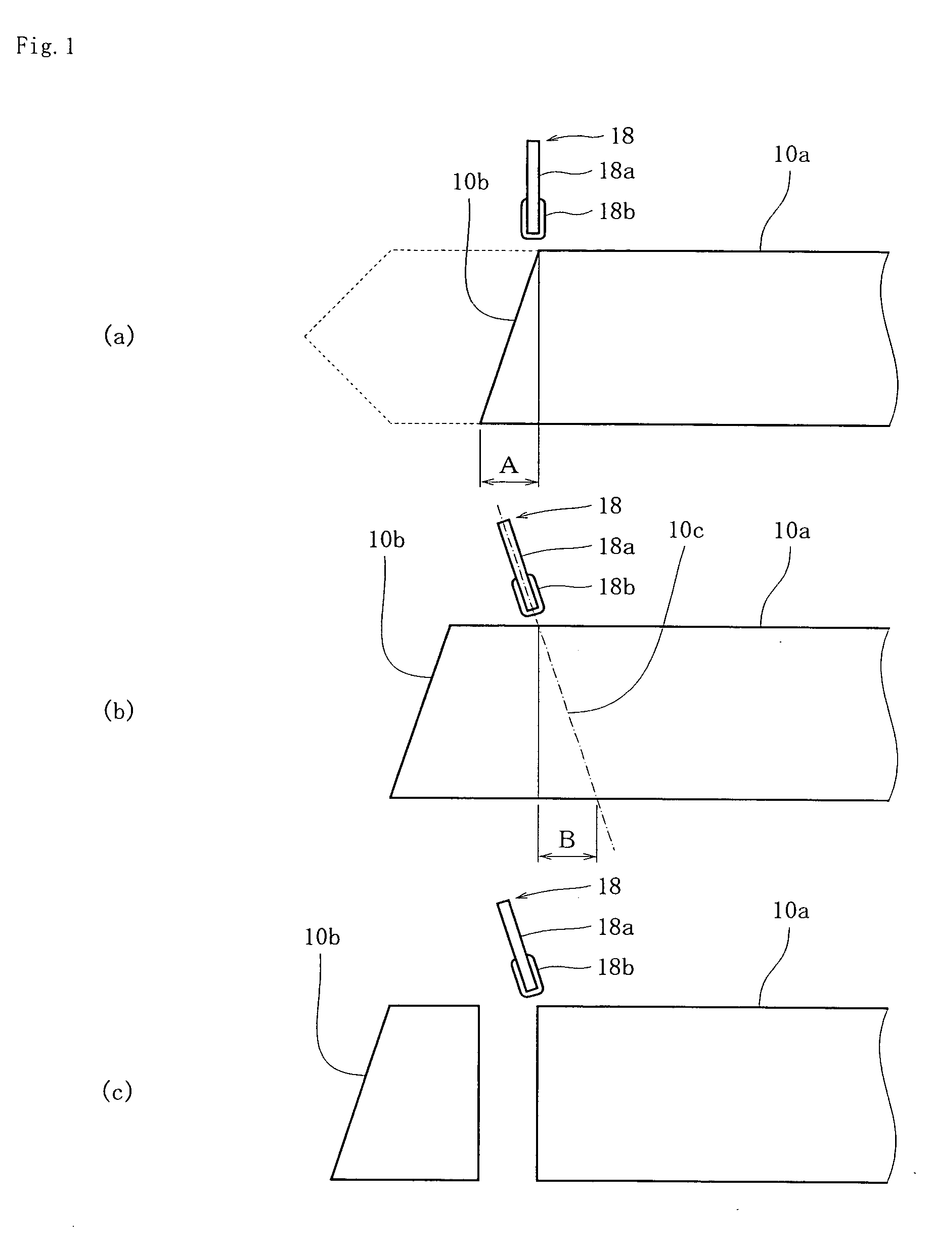
[0013] A feature of this aspect of the invention is the correction of the inclination, if any, of the blade with respect to an ingot 10a to be cut as shown in FIG. 1: if the blade is inclined by a certain angle with respect to a line vertical to the longitudinal axis of an ingot 10a and the inclination produces a shift A at the lowest end of cut surface 10b, the cutting machine detects the shift A, and corrects the inclination of the blade with respect to the ingot 10a so as to cancel out the shift A by tilting the imaginary cut surface 10c including the straightly running portion 18a of the blade in the opposite direction by a certain angle with respect to a line vertical to the longitudinal axis of ingot 10a, calculating an expected shift B obtained at the lowest end of imaginary cut surface 10c, when ingot 10a is assumed to be cut by the tilted blade, between the uppermost end of imaginary cut surface 10c and its lowermost end projected to the longitudinal axis of ingot 10a, and adjusting the tilted angle such that shift B is equal to shift A. An additional feature of this aspect of the invention is to momentarily correct the inclination of the straightly running portion 18a of the blade if any, and to continue the cutting with the corrected blade thereafter without interruption.
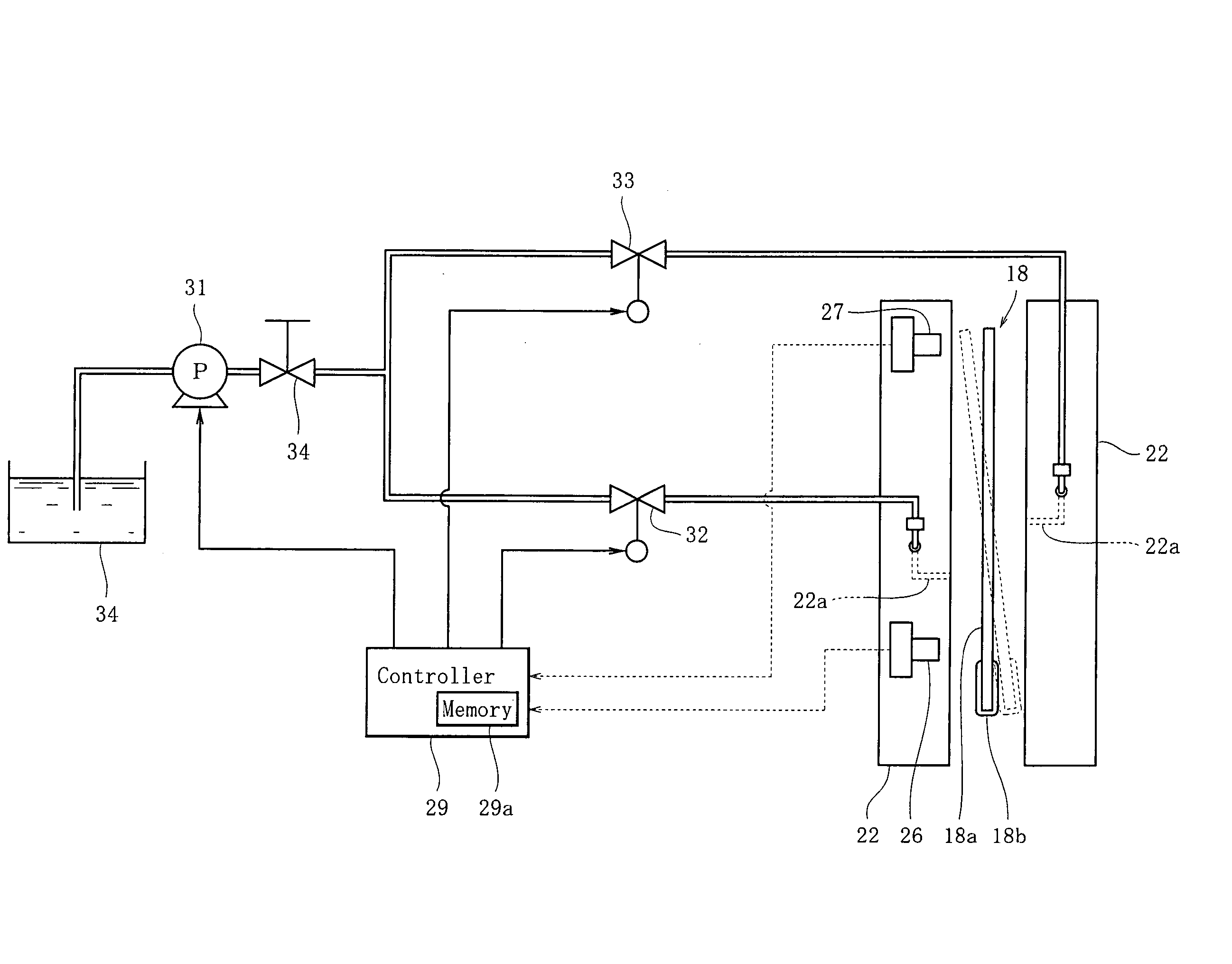
[0017] According to the method as described in claim 2 for cutting a single crystal ingot, if the straightly running portion 18a of the blade is inclined to one side, correction of the inclination is achieved by applying fluid jets from the nozzles provided to the pair of opposed members to the inclined blade. Therefore, it is comparatively easy to return the inclined straightly running portion 18a of the blade to a desired position by appropriately adjusting the pressures wrought by those fluid jets. The pair of opposed members 22, 22 has space between them so wide as to allow the blade to run through the space without touching the members which will contribute to the lengthening of life of the involved members, i.e., the pair of opposed members and blade.
[0019] According to an embodiment of the invention, a band saw type cutting machine further comprises a pair of opposed members on both sides of a straight course the blade runs during cutting, the pair of members being equipped with respective nozzles. If the straightly running portion of the blade is inclined to one side, correction of the inclination is achieved by applying fluid jets from the nozzles provided to the pair of opposed members to the inclined blade. Therefore, it is comparatively easy to return the inclined straightly running portion of the blade to a desired position by appropriately adjusting the pressures wrought by those fluid jets. Moreover, once correction of the inclination of the blade is achieved, application of fluid jets to the surfaces of the blade engaged in cutting is withdrawn which keeps the blade from being exposed to the change of pressure, and relieves the surfaces of cut slices of step-like undulations. Furthermore, since correction of the blade is based only on tilting and does not include any bending, tension of the blade 18 does not change in any way due to the correction operation. Thus, shortening of life of the blade which would result if tension were increased as a result of correction can be safely avoided.

Problems solved by technology

However, if the straight course the blade takes during running is made too long, the blade will be more prone to sideward swings which, if present, will degrade the cut precision of the cutting machine.
However, natural cleaning of diamond particles does not occur evenly over the blade.
The blade having a skewed predilection in the cutting direction will degrade the precision of cutting unless properly treated.
However, if such a blade is inclined to a preferred direction divergent from a normal specified direction during cutting, it is hardly possible, according to the aforementioned conventional method, to forcibly push back the inclined blade by applying fluid jet to the blade because the inclining tendency of the blade is inherent to the blade itself.
This makes it difficult to achieve the stable cutting of ingots.
Moreover, because the pressure wrought by the fluid jet acts in a direction normal to the direction in which the blade runs during cutting, the tension of the blade is enhanced, giving extra stresses to the blade which will shorten the due life of the blade.

Method used


Image

  • Method for cutting a single crystal ingot
  • Method for cutting a single crystal ingot
  • Method for cutting a single crystal ingot

Examples


Embodiment Construction

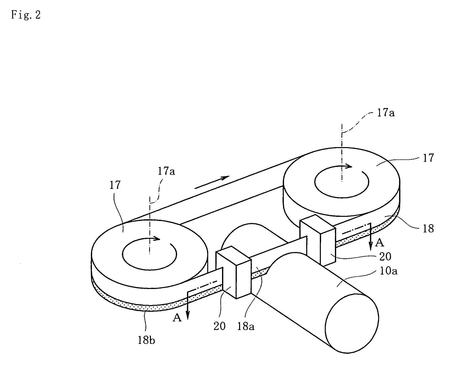
[0028] The embodiments representing the best mode of application of the present invention will be described with reference to the attached drawings.

[0029]FIGS. 7 and 8 represent a cutting machine 10 used according to the present invention for cutting single crystal ingot. The cutting machine 10 comprises a platform 11 for supporting an ingot 10a horizontally, and, in front of the platform 11, an inverted U-shaped frame 12 encompassing the platform 11. On the platform 11, there is provided a table 13 for carrying an ingot 10a thereon which is movable in an anterior-posterior direction. On the table 13 there is provided a base 14 for directly supporting the ingot 10a. In order to ensure the cutting of ingot 10a to occur at specified levels, there are provided notches whose profile is v-shaped (not illustrated) on the base 14 at specified positions where the ingot 10a will be cut such that, when a below-described blade 18 cuts ingot 10a at a specified position, the notch can receive t...


PUM

PropertyMeasurementUnit
Angleaaaaaaaaaa

Abstract

The object of the present invention is to provide a method whereby it is possible to cut a single crystal ingot comparatively accurately while allowing resulting slices to have a flat surface, and to lengthen the life of the blade more than would be possible with conventional methods. A single crystal ingot 10a is arranged below a straightly running portion 18a of the blade which is made to run endlessly along a circuit such that the longitudinal axis of ingot 10a crosses at right angles with the straightly running portion 18a of the blade, thereby enabling the straightly running portion 18a of the blade to cut the ingot 10a perpendicularly. If the blade is inclined to one side, the cutting machine detects a shift A between the uppermost end of cut surface 10b and its lowermost end projected to the longitudinal axis of ingot, and corrects the inclination of the blade by tilting the imaginary cut surface 10c including the straightly running portion of the blade in the opposite direction by an angle with respect to a line vertical to the longitudinal axis of ingot 10a such that shift B is equal to shift A. Subsequent to correction, cutting is further continued with the straightly running portion 18a of the blade whose inclination has been just corrected

Description

CROSS-REFERENCES TO RELATED APPLICATIONS [0001] This application claims priority of Japanese Application No. 2005-032040 filed Feb. 8, 2005, the entire disclosure of which is hereby incorporated by reference. BACKGROUND OF THE INVENTION [0002] 1. Field of the Invention [0003] The present invention relates to a method for cutting a single crystal ingot wherein a straightly running portion of the endless circuiting blade is used for cutting a single crystal ingot. [0004] 2. Description of the Related Art [0005] Conventionally, with regard to cylindrical single crystal ingots which serve as a material of silicon wafers, the CZ method has been mainly used for the manufacture of ingots having a diameter of 8 inch or less. When a cylindrical single crystal ingot is produced by the CZ method, it has its top and tail portions removed before it is sliced into wafers. The remaining body portion is divided by cutting into several blocks and some wafers are sampled from those blocks. In order t...

Claims


Application Information

Patent Timeline
IPC IPC(8): B28D1/08
CPCB23D55/084B28D1/086B28D5/0064B28D5/045Y10T83/089
Inventor YAMASAKI, MASAHIKOOHIGASHI, YOSHITSUGU
Owner SUMCO CORP
Learn More