
Plasmonic enhanced infrared detector element

Active Publication Date: 2006-08-10
STC UNM
View PDF3 Cites 85 Cited by
  • Summary
  • Abstract
  • Description
  • Claims
  • Application Information

AI Technical Summary

Problems solved by technology

The sensitivity of all of these detectors is ultimately limited by several sources of noise.
Most infrared detectors—especially as the detector temperature is increased towards room temperature—are limited by various effects such as thermal generation of electrons and holes and junction leakage that generally scale with the area of the device.
Despite the vast amount of work on antennas at RF and microwave frequencies, relatively little has been done on antennas for infrared frequencies.
This is largely because the scale of the photon wavelength (˜several micrometers) is quite challenging and until relatively recently, available fabrication has not been up to the manufacturing challenge.

Method used


Image

  • Plasmonic enhanced infrared detector element
  • Plasmonic enhanced infrared detector element
  • Plasmonic enhanced infrared detector element

Examples


Embodiment Construction

[0024] Reference will now be made in detail to exemplary embodiments of the invention, examples of which are illustrated in the accompanying drawings. Wherever possible, the same reference numbers will be used throughout the drawings to refer to the same or like parts.

[0025] Notwithstanding that the numerical ranges and parameters setting forth the broad scope of the invention are approximations, the numerical values set forth in the specific examples are reported as precisely as possible. Any numerical value, however, inherently contains certain errors necessarily resulting from the standard deviation found in their respective testing measurements. Moreover, all ranges disclosed herein are to be understood to encompass any and all sub-ranges subsumed therein. For example, a range of “less than 10” can include any and all sub-ranges between (and including) the minimum value of zero and the maximum value of 10, that is, any and all sub-ranges having a minimum value of equal to or gr...


PUM


Abstract

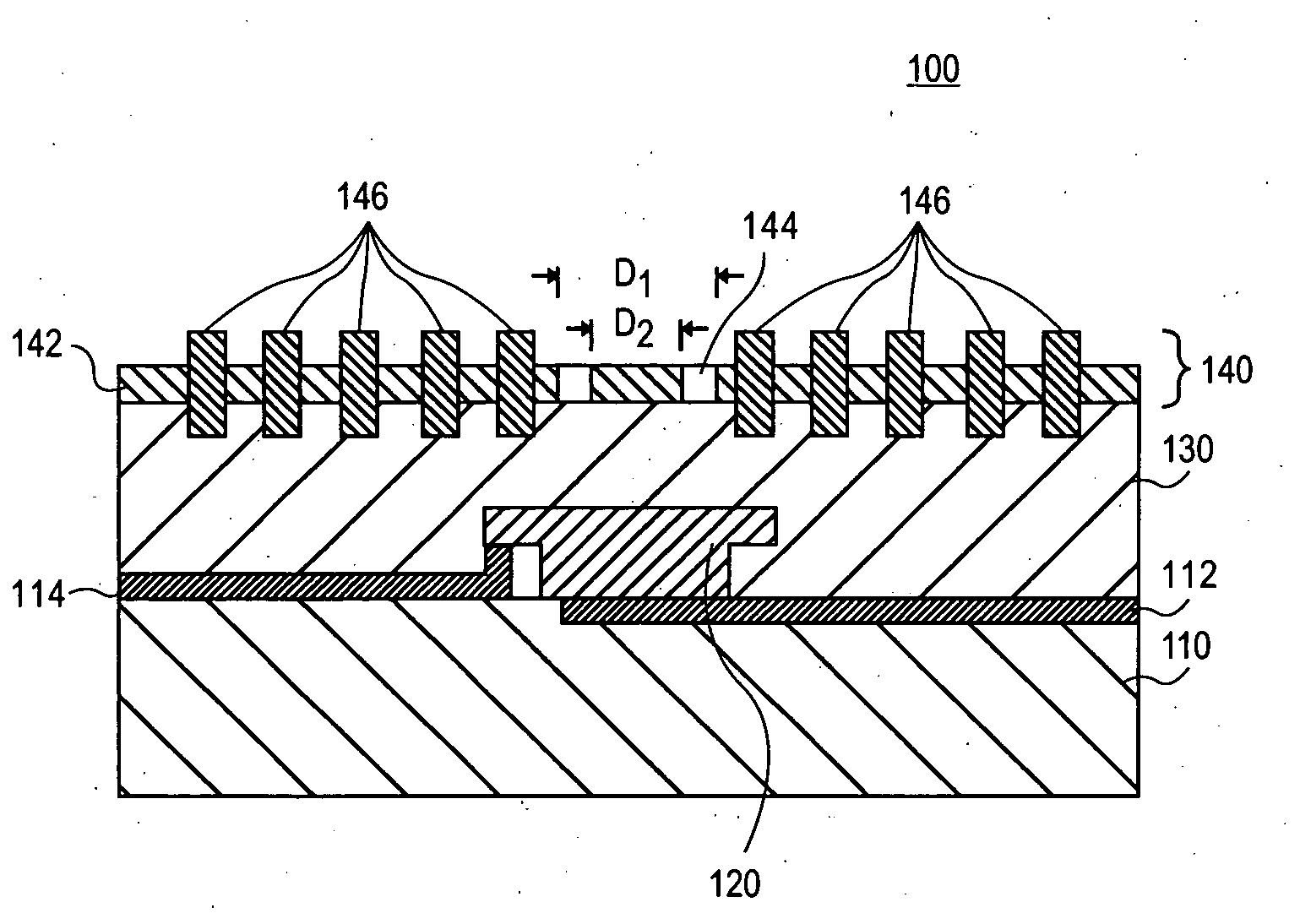
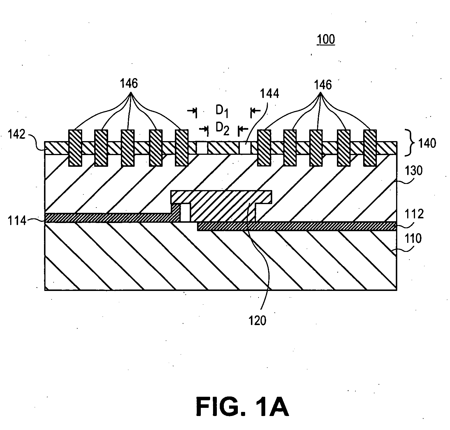
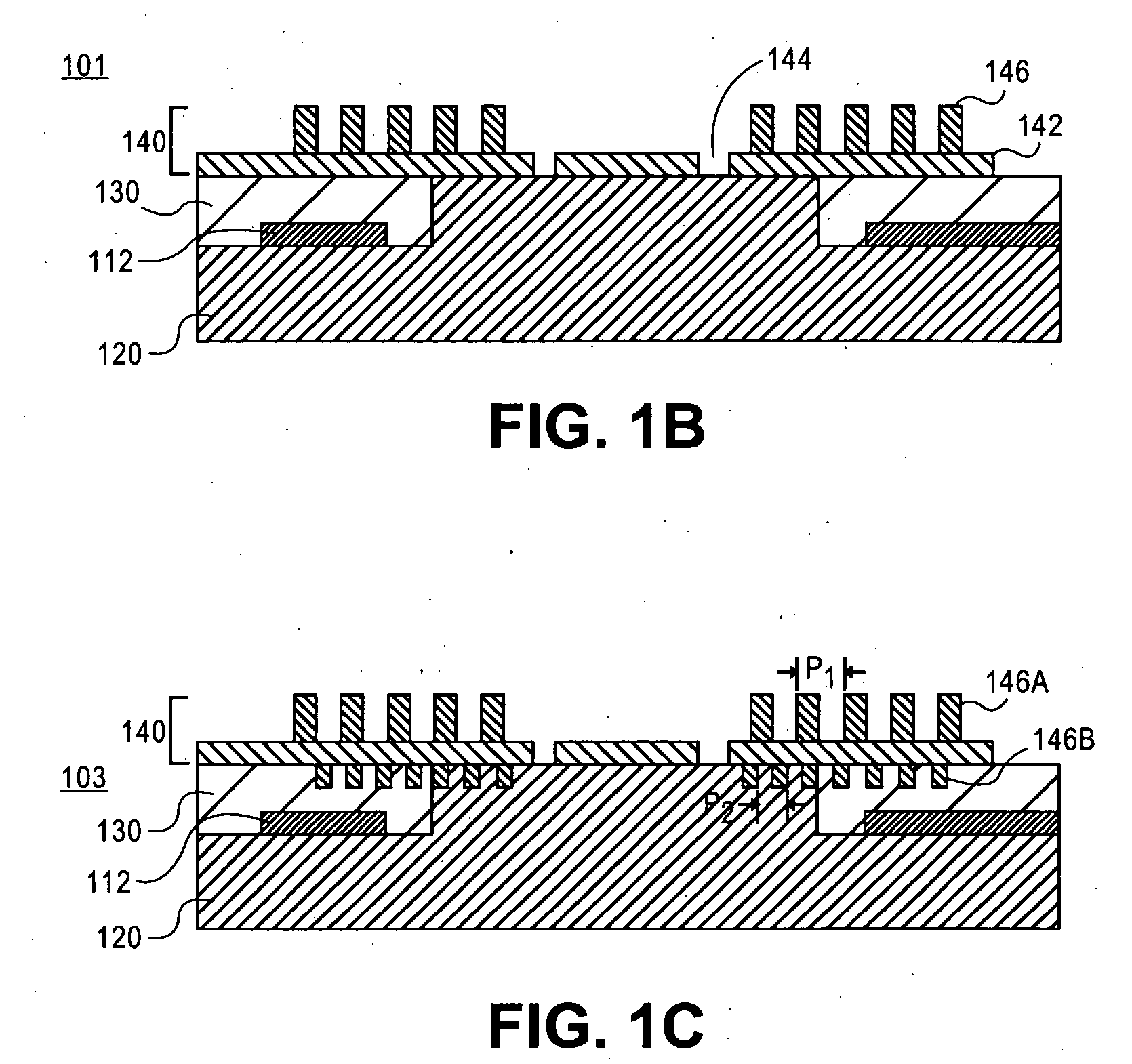
Electromagnetic radiation detector elements and methods for detecting electromagnetic radiation, in particular, infrared radiation, are provided. The electromagnetic radiation detector element can include an electromagnetic radiation detector and a plasmonic antenna disposed over the electromagnetic radiation detector. The plasmonic antenna can include a metal film, a sub-wavelength aperture in the metal film, and a plurality of circular corrugations centered around the sub-wavelength aperture.

Description

CROSS REFERENCE TO RELATED APPLICATIONS [0001] This application claims priority from U.S. Provisional Patent Application Ser. No. 60 / 649,572, filed Feb. 4, 2005, which is incorporated by reference herein in its entirety.FIELD OF THE INVENTION [0002] The present invention generally relates to antennas and, more particularly, to antennas for electromagnetic radiation detectors. BACKGROUND OF THE INVENTION [0003] The infrared spectral region is important for a number of reasons. The peak of the room temperature blackbody radiation spectrum is at about 10 μm. Thus, everything necessarily exchanges energy with the radiation field at infrared wavelengths and there is information on temperature, emissivity, etc. contained in the radiation field. At night, this radiation can be used to visualize the environment and to find particularly “hot” objects—such as, for example, people and engines. Because this makes the spectral region important for defense applications, the military has had a lon...

Claims


Application Information

Patent Timeline
IPC IPC(8): G01J5/02
CPCG01J5/02G01J5/022G01J5/08G01J5/0837G01J5/10
Inventor FAN, WENJUNZHANG, SHUANGMALLOY, KEVIN J.BRUECK, STEVEN R. J.
Owner STC UNM
Learn More