Claw-pole electric generator and bicycle electric generator hub

Inactive Publication Date: 2006-08-10
SHIMANO SINGAPORE PRIVATE LTD
View PDF16 Cites 7 Cited by
  • Summary
  • Abstract
  • Description
  • Claims
  • Application Information

AI Technical Summary

Benefits of technology

[0013] An object of the present invention is to suppress the weight increase and to ensure that the yoke external peripheral parts do not

Problems solved by technology

In the latter conventional electric generator, if the angles of curvature of the yoke external peripheral parts differ even slightly, the external peripheral surface of the yoke may b

Method used


Image

  • Claw-pole electric generator and bicycle electric generator hub
  • Claw-pole electric generator and bicycle electric generator hub
  • Claw-pole electric generator and bicycle electric generator hub

Examples


second embodiment

[0070] Referring now to FIG. 11, a generator hub in accordance with a second embodiment will now be explained. In view of the similarity between the first and second embodiments, the parts of the second embodiment that are identical to the parts of the first embodiment will be given the same reference numerals as the parts of the first embodiment. Moreover, the descriptions of the parts of the second embodiment that are identical to the parts of the first embodiment may be omitted for the sake of brevity.

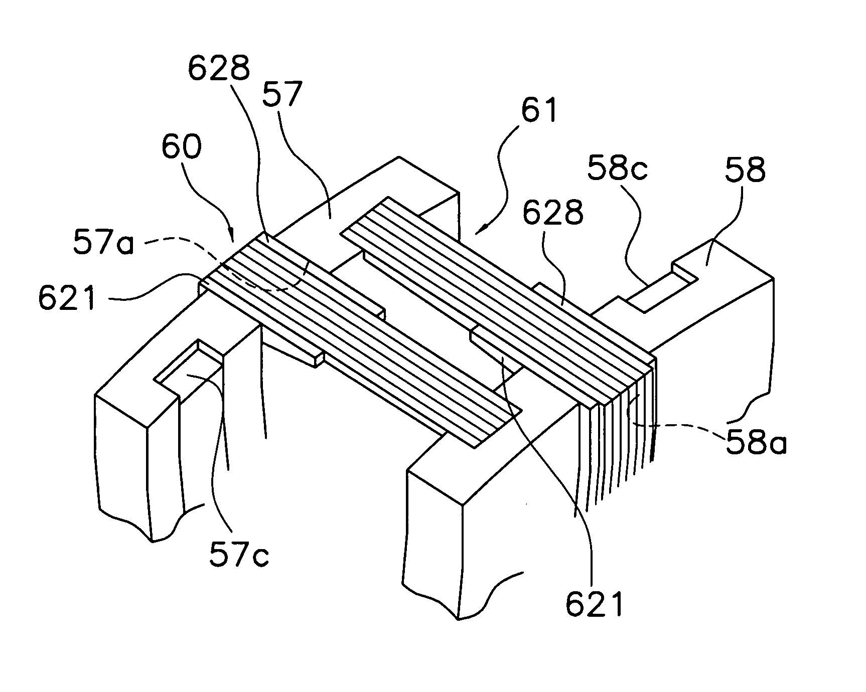
[0071] The previous embodiment disclosed a yoke 46 obtained by stacking the plate-shaped pieces 62 in the circumferential direction, but the present invention can also be applied to a yoke 146 in which a plurality of plate-shaped pieces 162 is stacked in the axial direction of the hub 10, as shown in FIG. 11.

[0072] The yoke 146 has a stator yoke portion 147 and a core yoke portion 148. The stator yoke portion 147 is disposed between the permanent magnet 41 and the coil 44. The cor...


PUM


Abstract

A claw-pole electric generator has a circumferentially arranged permanent magnet, a ring-shaped coil, a yoke and a cover member. The yoke surrounds an external periphery of the coil. The yoke has a stator yoke portion and a core yoke portion. The stator yoke portion is disposed between the coil and the permanent magnet. The core yoke portion is magnetically linked to the stator yoke portion. The core yoke is disposed on the external periphery of the coil. The coil and the yoke are rotatably disposed in relation to the permanent magnet. The stator yoke portion includes a plurality of first and second yoke sections having a plurality of plate-shaped pieces in a stacked arrangement on opposite sides of the coil in an axial direction. The cover member covers at least part of an external peripheral surface of the yoke section.

Description

CROSS-REFERENCE TO RELATED APPLICATIONS [0001] This application claims priority under 35 U.S.C. § 119 to Japanese Patent Application No. 2005-029540. The entire disclosure of Japanese Patent Application No. 2005-029540 is hereby incorporated herein by reference. BACKGROUND OF THE INVENTION [0002] 1. Field of the Invention [0003] The present invention generally relates to a claw-pole electric generator and a bicycle electric generator hub that uses the same. [0004] 2. Background Information [0005] Bicycle electric generator hubs that use claw-pole electric generators are known in the art. In some conventional claw-pole electric generators, a yoke is configured from a plurality of first and second stacked yokes obtained by stacking plate-shaped pieces. The conventional claw-pole electric generators configured from stacked yokes include those in which the plate-shaped pieces are formed into a C shape and have a yoke internal peripheral part, a yoke external peripheral part and a core p...

Claims


Application Information

Patent Timeline
IPC IPC(8): H02K1/12
CPCB62J6/12H02K1/145H02K7/1846H02K21/227
Inventor YOSHIDA, FUMINORI
Owner SHIMANO SINGAPORE PRIVATE LTD
Why Eureka
Try Eureka