Vehicle subframe

a subframe and vehicle technology, applied in the field of vehicles, can solve the problems that the vertical length of the rear end of the differential device to the vertical plate portion of the reinforcing plate member cannot be guaranteed, and achieve the effect of maintaining the required productivity, simple configuration, and high layout flexibility

Active Publication Date: 2016-12-01
F TECH INC
View PDF1 Cites 8 Cited by
  • Summary
  • Abstract
  • Description
  • Claims
  • Application Information

AI Technical Summary

Benefits of technology

[0014]According to the configuration of the first aspect of the present invention, one of the pair of cross members includes the lower member open to the lower side of the vehicle, with the upper wall thereof having the upper wall recess depressed downward, the tipper member arranged so as to cover the upper wall recess from above the vehicle and connected to the lower member, the inside space defined by the lower member and the upper member in cooperation, and the holding member connected to the lower member and the upper member in the mode in which the holding member is sandwiched between the lower member and the upper member, while penetrating the inside space in the longitudinal direction, to hold the component to be mounted. Accordingly, a vehicle subframe that can reliably mount the component to be mounted without increasing a space occupied by the subframe can be realized. Further, a vehicle subframe that can configure the holding portion of the component to be mounted with high layout flexibility with a simple configuration, while maintaining required productivity, and can improve the support strength and stiffness or the suspension arm can be provided.
[0015]According to the configuration of the second aspect of the present invention, the holding member is arranged to be deviated from the central portion of the lower member and the upper member in the width direction, and the lower member has a lower recess depressed toward the upper side of the vehicle and arranged with the holding member in the width direction. Accordingly, even if the component to be mounted is arranged to be deviated in the width direction, a difference in the strength and stiffness in the width direction can be decreased, while improving the strength and stiffness of the subframe in a mode that does not degrade the layout flexibility.
[0016]According to the configuration of the third aspect of the present invention, the rear cross member includes the first member having the first vertical wall and the first upper wall continuous to the first vertical wall, and the second member having the second vertical wall facing the first vertical wall in the longitudinal direction and the second upper wall continuous to the second vertical wall and connected to the first upper wall. The plate thickness of the first member is set to be equal to or larger than that of the second member. Accordingly, the component to be mounted can be mounted, while suppressing an unnecessary increase in weight of the rear cross member, and the support strength and support stiffness of the suspension arm can be improved.
[0017]According to the configuration of the fourth aspect of the present invention, the reinforcing member that connects the rear cross member with the front cross member is further arranged. Accordingly, an input load in the longitudinal direction from the component to be mounted and the suspension arm can be reliably received.
[0018]According to the configuration of the fifth aspect of the present invention, the front cross member includes the third member having the third vertical wall, the third upper wall continuous to the third vertical wall, and the third lower wall continuous to the third vertical wall, and the fourth member having the fourth vertical wall facing the third vertical wall in the longitudinal direction, the fourth upper wall continuous to the fourth vertical wall and connected to the third upper wall, and the fourth lower wall continuous to the fourth vertical wall and connected to the third lower wall. The plate thickness of the third member is set to be equal to or larger than that of the fourth member. Accordingly, an input load from the rear cross member can be reliably received, while suppressing an unnecessary increase in weight of the front cross member.
[0019]According to the configuration of the sixth aspect of the present invention, the reinforcing member connects the first member with the fourth member. Accordingly, the required strength and stiffness can be maintained, while further suppressing the unnecessary increase in weight of the front cross member and the rear cross member.

Problems solved by technology

However, according to studies made by the present inventor, in Japanese Patent Application Laid-open Publication No. 2000-272535, such a case can be considered that a vertical length for attaching the rear end of the differential device to the vertical plate portion of the reinforcing plate member may not be ensured, according to the layout of peripheral components.

Method used


Image

  • Vehicle subframe
  • Vehicle subframe
  • Vehicle subframe

Examples


Embodiment Construction

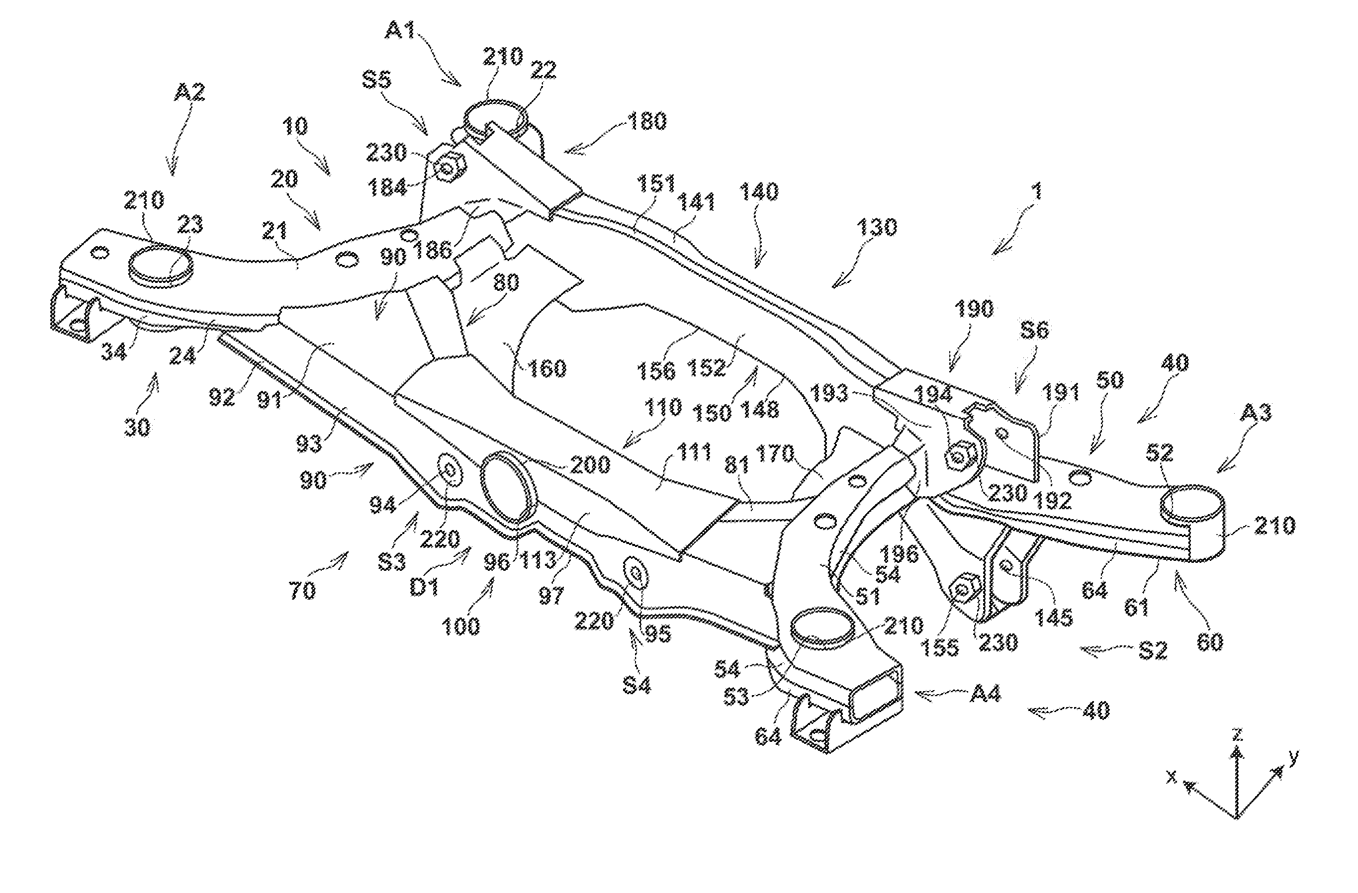
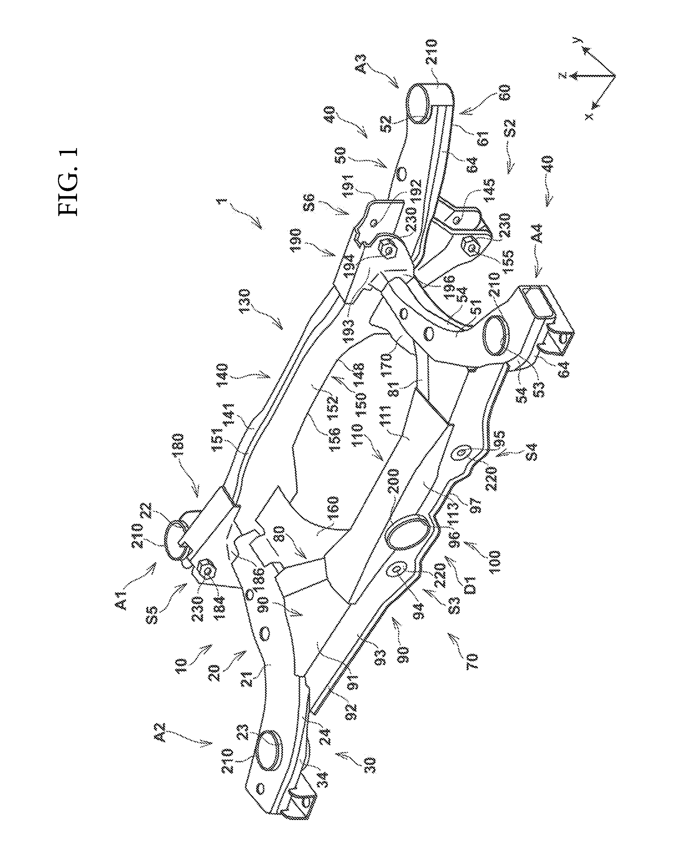
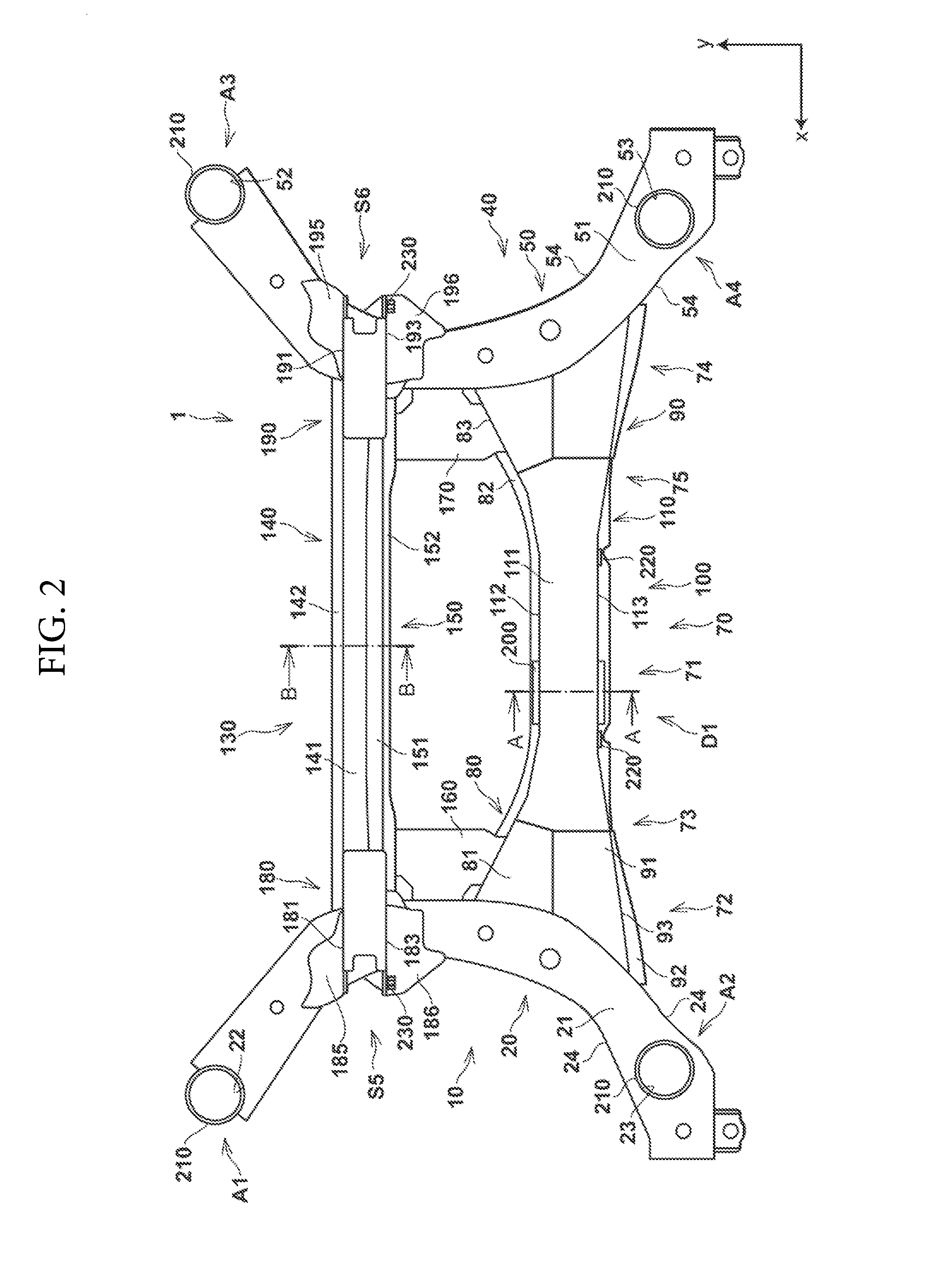
[0026]A vehicle subframe according to an embodiment of the present invention is explained in detail below with reference to FIGS. 1 to 6 as appropriate. In the drawings, an x-axis, a y-axis, and a z-axis form a three-dimensional orthogonal coordinate system. A positive direction of the x-axis is a left direction of a vehicle body, a positive direction of the y-axis is a forward direction of the vehicle body, and a positive direction of the z-axis is an upper direction of the vehicle body. The x-axis direction may be referred to as “width direction”, and the y-axis direction may be referred to as “longitudinal direction”.

[0027]FIG. 1 is a perspective view of a vehicle subframe according to an embodiment of the present invention, FIG. 2 is a plan view of the vehicle subframe according to the present embodiment, FIG. 3 is a bottom view of the vehicle subframe according to the present embodiment, FIG. 4 is a sectional view along a line A-A in FIG. 2, and FIG. 5 is a sectional view along...


PUM


Abstract

In a vehicle subframe, one of a pair of cross members includes a lower member open to a lower side of a vehicle, with an upper wall thereof having an upper wall recess depressed downward, an upper member arranged so as to cover the upper wall recess from above the vehicle and connected to the lower member, an inside space defined by the lower member and the upper member in cooperation, and a holding member connected to the lower member and the upper member in a mode in which the holding member is sandwiched between the lower member and the upper member, while penetrating the inside space in a longitudinal direction, to hold a component to be mounted.

Description

BACKGROUND OF THE INVENTION[0001]The present invention relates to a vehicle subframe, and more particularly relates to a vehicle subframe that supports a suspension arm, a differential device (an actuator), and the like and is mounted on a vehicle such as an automobile.[0002]In recent years, the subframe mounted on a vehicle such as an automobile receives a large input load such as a tensile load and a compressive load from respective arms particularly generated at the time of turning or braking, due to improvement of turning performance and braking performance of the vehicle.[0003]Therefore, with respect to such a subframe, it has been required to further increase the strength and stiffness of the subframe, while maintaining productivity thereof.[0004]Under such circumstances, Japanese Patent Application Laid-Open Publication No. 2000-272535 relates to a vehicle subframe structure and discloses a configuration including a vehicle width-direction extending member and a reinforcing p...

Claims


Application Information

Patent Timeline
Patent Type & Authority Applications(United States)
IPC IPC(8): B62D21/08B62D21/11
CPCB62D21/11B62D21/08
Inventor YOKOTA, TOMOYUKI
Owner F TECH INC
Why Eureka
Try Eureka