Display Device

Active Publication Date: 2007-03-29
PANASONIC LIQUID CRYSTAL DISPLAY CO LTD +1
View PDF5 Cites 12 Cited by
  • Summary
  • Abstract
  • Description
  • Claims
  • Application Information

AI Technical Summary

Benefits of technology

[0039] The present invention is applied to, for example, an active matrix substrate on which quasi-strip crystalline silicon films are prepared as silicon films to form a drive circuit around each pixel area. The quasi-crystalline silicon films are prepared by irradiating specific sections of a silicon film by a continuous-wave laser or the like to selectively reform the silicon film. Since the boundary between each quasi-strip crystalline film and a non-reformed semiconductor film can be used effectively, it is possible to improve the space utilization and raise the circuit layout flexibility.
[0040] Further, since the circuit fabrication space on the substrate can be used more efficiently, the area to be irradiated for reformation to quasi-strip crystalline semiconductor can be reduce

Problems solved by technology

It is not possible to dispose thin film transistors in the boundary of the quasi-strip crystalline section.
Standing

Method used


Image

  • Display Device
  • Display Device
  • Display Device

Examples


embodiment 1

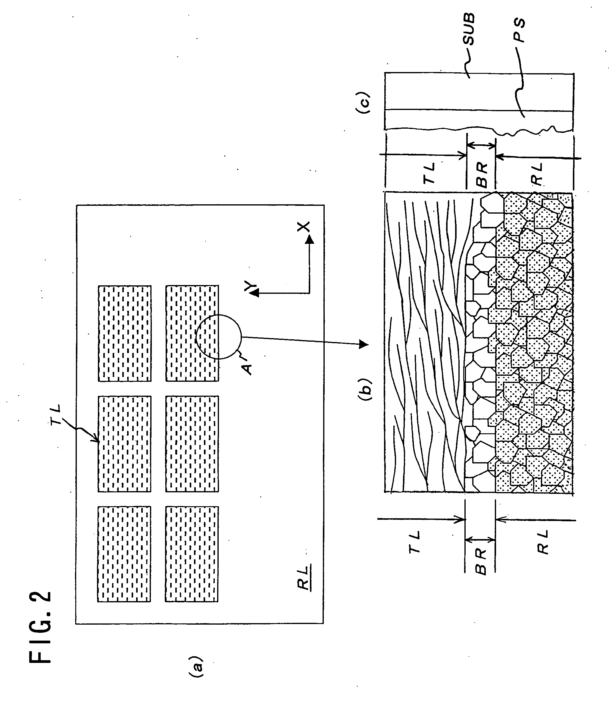
[0062] FIGS. 4(a) to 4(d) schematically show a first embodiment, a layout of thin film transistors in a substrate area having a quasi-strip crystalline section TL and a different-crystallinity section RL thereon as shown in FIGS. 2(a) to 2(c). In FIGS. 4(a) to 4(d), each component which has the same function as the corresponding one in FIGS. 3(a) to 3(d) are given the same referential name as in FIGS. 3(a) to 3(d). In the first embodiment, silicon islands ALD1, ALD2, ALD3 and ALD6 are formed by patterning one quasi-strip crystalline section TL. As well, silicon islands ALD4, ALD5, ALD7 and ALD8 are formed by patterning the different-crystallinity section RL. The semiconductor film of the boundary section BR is partly left.

[0063] In FIG. 4(a), the island ALD1 in the quasi-strip crystalline section TL and the island ALD4 in the grain-crystalline section RL are integrated as a single island via the boundary section BR. That is, a conductive line or resistor which connects the thin fil...

embodiment 2

[0068] FIGS. 5(a) to 5(d) schematically show a second embodiment, a layout of thin film transistors in a substrate area having quasi-strip crystalline sections TL and a different-crystallinity section RL thereon as shown in FIGS. 2(a) to 2(c). FIGS. 4(a) to 4(d) are different from FIGS. 2(a) to 2(c) only in that each quasi-strip crystalline section TL is smaller. In FIGS. 5(a) to 5(d), an island ALD1 is composed of three portions which are formed respectively from a quasi-strip crystalline section TL, a different-crystallinity section RL and a boundary section BR between them. Islands ALD2, ALD3 and ALD4 are also composed in the same manner.

[0069] Each of the thin film transistors in FIGS. 5(a), 5(b) and 5(d) uses a quasi-strip crystalline section TL to form its channel region.

[0070] In addition, each of the thin film transistors in FIGS. 5(a) and 5(b) uses the semiconductor film of the boundary section BR as a part of the conductive line or resistor connected to its channel regio...


PUM


Abstract

The present invention provides an active matrix display device capable of raising its integration density by reducing the drive circuit area on the active matrix substrate. A semiconductor film presents in the boundary between a quasi-strip crystalline semiconductor film and another semiconductor film is used to form conductive lines, resistors, source/drain electrodes and the like which are respectively connected to thin film transistors formed using the quasi-strip crystalline semiconductor film.

Description

CLAIM OF PRIORITY [0001] The present application claims priority from Japanese Application JP 2005-277985 filed on Sep. 26, 2005, the content of which is hereby incorporated by reference into this application. FIELD OF THE INVENTION [0002] The present invention is suitably applicable to an image display device and, more particularly, to an image display device in which the crystallinity of a semiconductor film formed on an insulating substrate is reformed to a strip-like crystalline structure with a laser beam and each drive circuit comprising an active element and others is formed using the reformed semiconductor film. BACKGROUND OF THE INVENTION [0003] Widely used active matrix image display devices comprise a matrix of active elements to constitute the drive system which drives the pixels arranged in a matrix form. Usually, in this kind of image display device, a great number of pixel circuits, each provided with an active element such as a thin film transistor (TFT) formed using...

Claims


Application Information

Patent Timeline
IPC IPC(8): G02F1/1343
CPCH01L27/13H01L27/1285H01L29/78645H01L29/04
Inventor MAKI, MASAHIROSATO, HIDEONAKAO, TAKAYUKIITOGA, TOSHIHIKO
Owner PANASONIC LIQUID CRYSTAL DISPLAY CO LTD
Why Eureka
Try Eureka