Modular high voltage distribution unit for hybrid and electrical vehicles

a high-voltage distribution and hybrid technology, applied in the direction of electric/fluid circuit, battery/cell propulsion, transportation and packaging, etc., can solve the problems of increasing complexity and manufacturing cost of the battery unit, the spacing and cut-outs of the individual connectors and fuse holes must be designed individually, and the arrangement maintenance problem, so as to achieve selective expansion and easy installation

Active Publication Date: 2012-08-23
SAMSUNG SDI CO LTD
View PDF8 Cites 12 Cited by
  • Summary
  • Abstract
  • Description
  • Claims
  • Application Information

AI Technical Summary

Benefits of technology

[0003]Embodiments relate to an arrangement which enables electrical power to be distributed from a battery to a plurality of different devices which are powered thereby. More specifically, embodiments relate to a

Problems solved by technology

For battery powered arrangements where a battery is used to supply power to a number of different devices such as in hybrid and/or electrically-powered vehicles, one problem is that during the battery design phase the spatial locations and cut-outs for the individual connectors and fuses must be designed individually, i.e., one-by-one.
Secondly, for each connector, wiring is

Method used


Image

  • Modular high voltage distribution unit for hybrid and electrical vehicles
  • Modular high voltage distribution unit for hybrid and electrical vehicles
  • Modular high voltage distribution unit for hybrid and electrical vehicles

Examples


Embodiment Construction

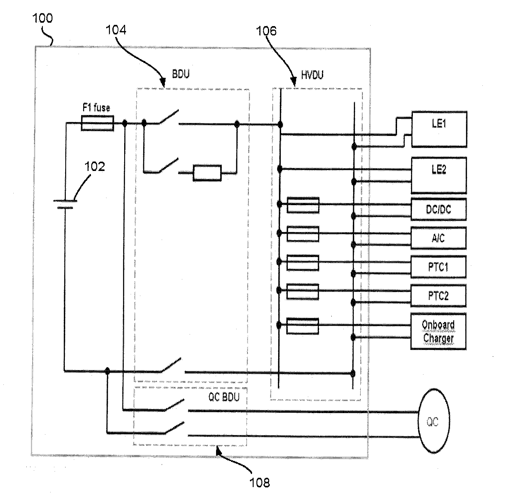
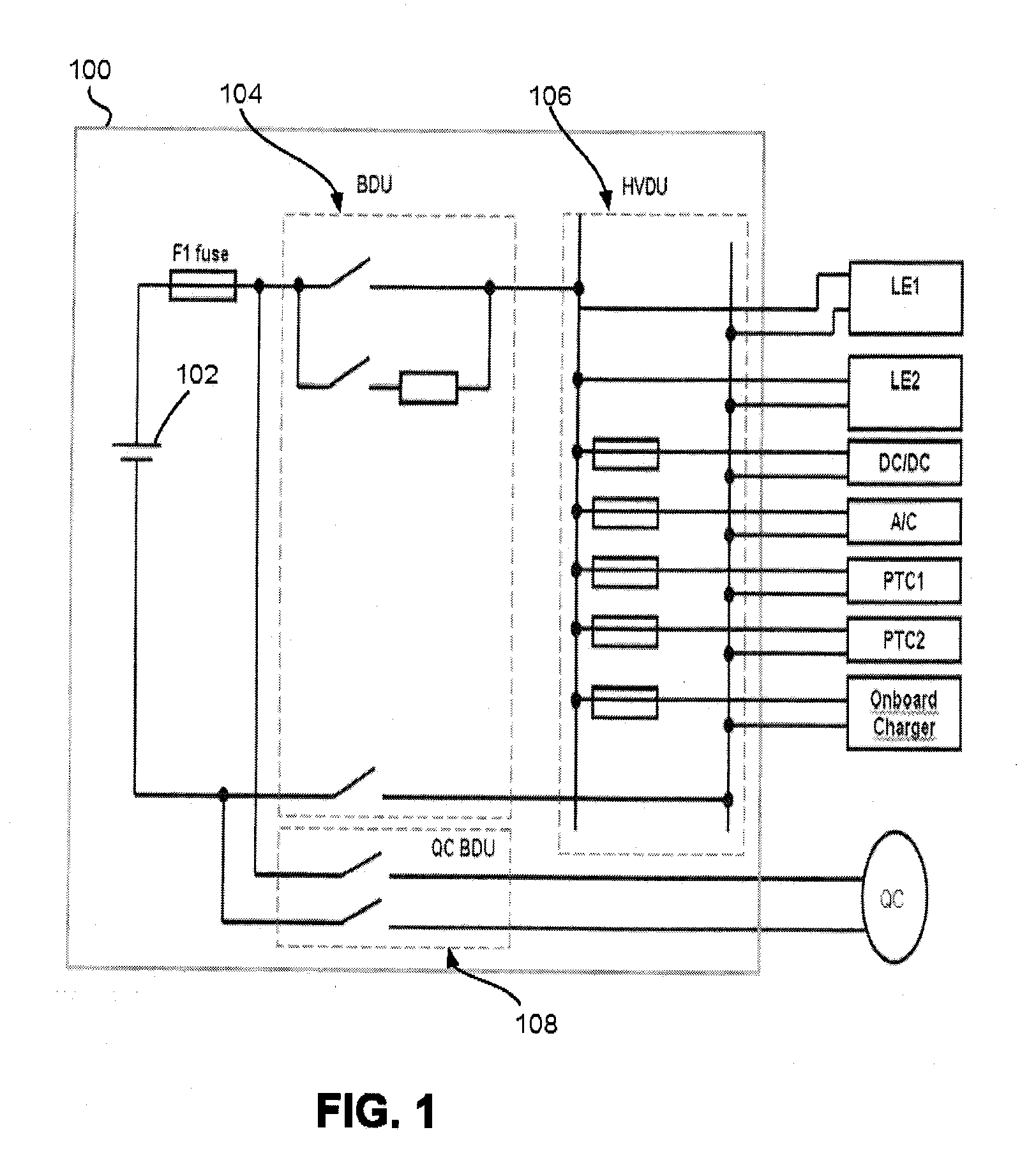
[0028]Example FIG. 1 illustrates a circuit arrangement of a battery system including battery casing 100 enclosing high voltage battery 102, battery disconnection unit (BDU) 104, high voltage distribution unit (HVDU) 106 and quick charge battery disconnection unit (QC BDU) 108. These arrangements are electrically connected or otherwise circuited in the illustrated manner with outboard devices LE1, LE2, DC / DC, A / C, PTC1, PTC2 and an onboard charger device. The QC BDU 108 is arranged to be connected with a quick charge device QC. Fuses are arranged in BDU and HVDU in the illustrated manner. High voltage battery 102 may be, for example, a battery capable of outputting 200-500 volts. Embodiments which are illustrated in example FIG. 1 are exemplary and not limiting to the scope thereof. Accordingly, embodiments may encompass modifications thereof.

[0029]In battery arrangements, battery casing 100 may require cabling and structure to enable the circuitry illustrated in example FIG. 1, and ...


PUM


Abstract

A distribution unit has an incomer module disposed on the exterior of a battery casing and electrically connected to a battery housed within the casing, and a plurality of feeder modules electrically daisy-chained to the incomer module and configured to respectively distribute electrical power from the battery to a plurality of individual electrically powered devices.

Description

CROSS-REFERENCE TO RELATED APPLICATIONS[0001]The present application claims priority under 35 U.S.C. §119 to U.S. Provisional Patent Application No. 61 / 304,071 (filed on Feb. 23, 2010), which is hereby incorporated by reference in its entirety.BACKGROUND OF THE INVENTION[0002]For battery powered arrangements where a battery is used to supply power to a number of different devices such as in hybrid and / or electrically-powered vehicles, one problem is that during the battery design phase the spatial locations and cut-outs for the individual connectors and fuses must be designed individually, i.e., one-by-one. Secondly, for each connector, wiring is required within the battery housing, which may lead to increased complexity and manufacturing cost of the battery unit. A third drawback is that it is necessary to guarantee package space on the surface of the battery casing / housing for the connections so as to allow for the various devices to be plugged in. A further disadvantage reside in...

Claims


Application Information

Patent Timeline
IPC IPC(8): H02B1/20
CPCB60R16/0238Y02T10/705Y02T10/7005B60L11/1879B60L50/64Y02T10/70
Inventor BARKOCZI, ROLAND
Owner SAMSUNG SDI CO LTD
Why Eureka
Try Eureka