Operating Oil Supplying Device and Construction Machine

Inactive Publication Date: 2011-01-20
KOMATSU LTD
View PDF16 Cites 13 Cited by
  • Summary
  • Abstract
  • Description
  • Claims
  • Application Information

AI Technical Summary

Benefits of technology

[0006]According to Patent Document 1, whose object is directed to improvement of the cleanability of a fan, the hydraulic oil from the turning pump is supplied to the hydraulic motor for driving the fan. In other words, it is not possible to supply the hydraulic oil from the hydraulic motor for driving the fan to the turning pump, and of course not possible to supply the hydraulic oil to a work equipment

Problems solved by technology

Such a large-sized hydraulic pump requires a h

Method used


Image

  • Operating Oil Supplying Device and Construction Machine
  • Operating Oil Supplying Device and Construction Machine
  • Operating Oil Supplying Device and Construction Machine

Examples


first exemplary embodiment

[1-1] Whole Structure of Dump Truck 1

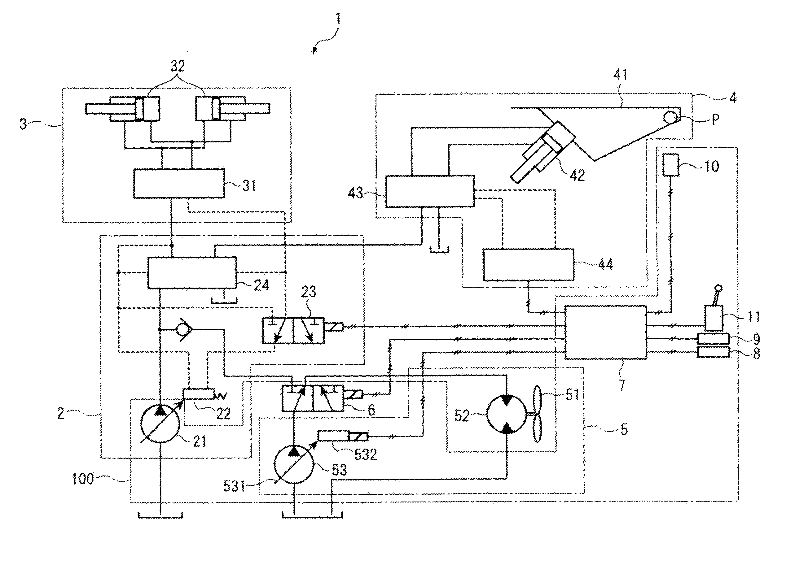
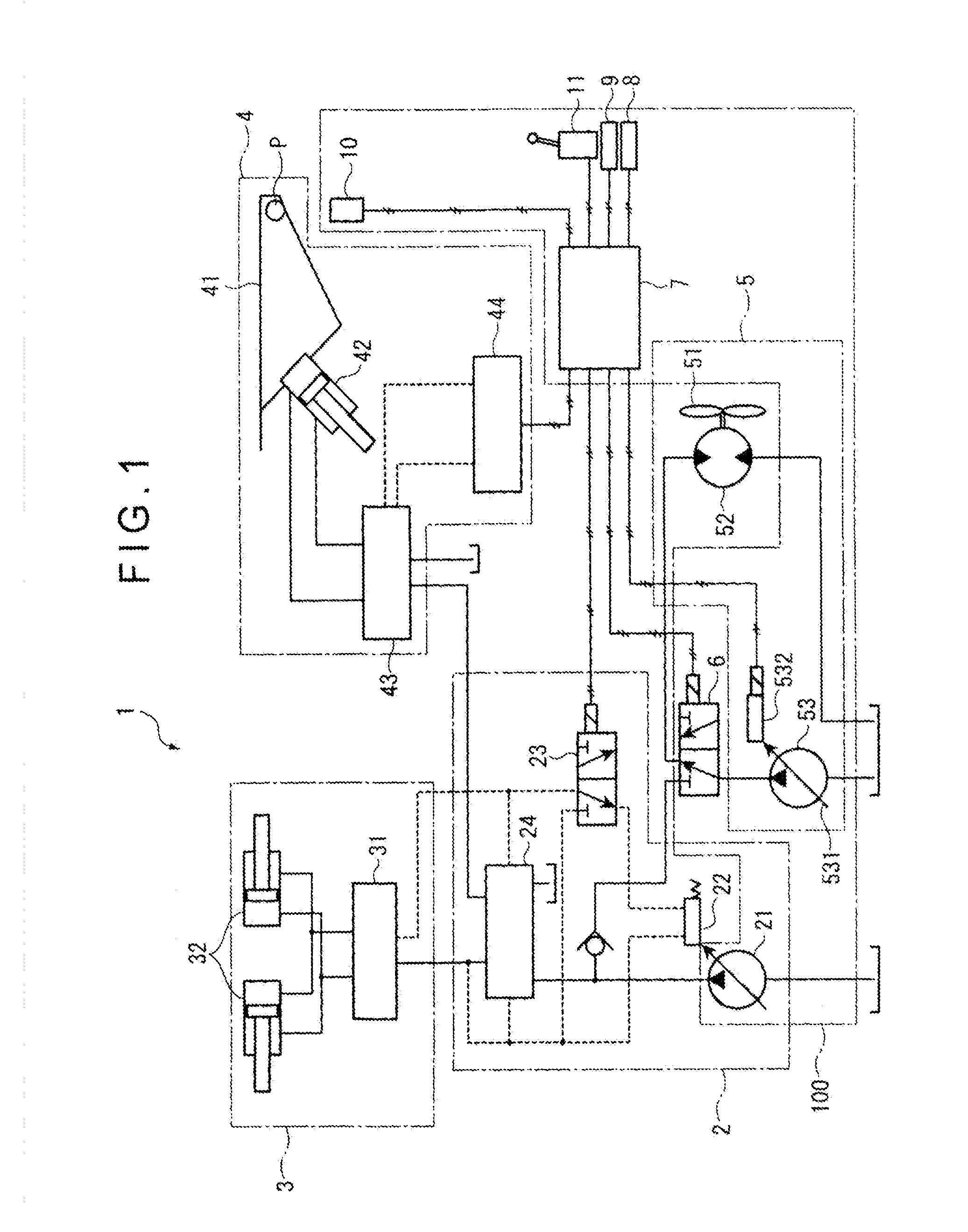
[0034]In FIG. 1 schematically showing the structure of a dump truck (construction machine) 1 according to a first exemplary embodiment, the dump truck 1 includes: a hydraulic oil supply amount adjuster 2; a steering mechanism driver 3; a work equipment driver 4; a fan driver 5; a circuit switching valve 6; and a controller 7.

[0035]The hydraulic oil supply amount adjuster 2 is a portion for adjusting the supply amount of a hydraulic oil supplied to the steering mechanism driver 3 and the work equipment driver 4. The hydraulic oil supply amount adjuster 2 includes: a work equipment pump 21; a load-sensing valve 22; a pilot pressure switching valve 23; and a priority valve 24. The work equipment pump 21 is a variable displacement hydraulic pump that is driven by an engine (not shown) as a power source and its discharge amount changes in accordance with the valve position of the load-sensing valve 22. The pilot pressure switching valve 23 is a positi...

second exemplary embodiment

[0066]Next, description will be made on a second exemplary embodiment of the invention with reference to FIG. 7.

[0067]In the above first exemplary embodiment, the dump truck 1 includes the steering mechanism driver 3 and the work equipment pump 21 supplies a hydraulic oil to the work equipment driver 4 and the steering mechanism driver 3.

[0068]In contrast, as shown in FIG. 7, in the second exemplary embodiment, the dump truck 1 does not include the steering mechanism driver 3, so that the operation pump 21 supplies a hydraulic oil only to the work equipment driver 4.

[0069]Specifically, the hydraulic oil supply amount adjuster 2 does not include the load-sensing valve 22, the pilot pressure switching valve 23 and priority valve 24 and the discharge-side of the work equipment pump 21 is hydraulically connected to the hoist cylinder 42.

[0070]With this arrangement, the controller 7 switches the valve position of the circuit switching valve 6 and performs the accompanying displacement co...

third exemplary embodiment

[0071]Next, description will be made on a third exemplary embodiment of the invention with reference to FIG. 8.

[0072]In the above first exemplary embodiment and second exemplary embodiment, the controller 7 performs the circuit switching when the input state of the body control lever 1 is set at the “up” state of the body 41 under the condition that the circuit switching is permitted.

[0073]In contrast, in the third exemplary embodiment, the controller 7 refers not only to the input state of the body control lever 11 but also to an accelerator pedal angle and performs the circuit switching when the input state of the body control lever 11 is set at the “up” state of the body 41 and the accelerator pedal angle is equal to or larger than a predetermined value.

[0074]Specifically, as shown in FIG. 8, the hydraulic oil supply device 100 according to this exemplary embodiment includes an accelerator pedal angle sensor 12 that is electrically connected to the input-side of the controller 7....


PUM


Abstract

A hydraulic oil supply device includes: a work equipment pump that supplies a hydraulic oil to a hydraulic actuator that drives a work equipment; a fan pump that supplies the hydraulic oil to a hydraulic motor that drives a cooling fan; and a circuit switching valve provided on a hydraulic circuit being branched from a hydraulic circuit connecting the hydraulic actuator with the work equipment pump to be connected to the fan pump, the circuit switching valve selectively connecting a discharge portion of the fan pump to the hydraulic actuator and the hydraulic motor.

Description

TECHNICAL FIELD[0001]The invention relates to a hydraulic oil supply device and a construction machine.BACKGROUND ART[0002]In a construction machine, a hydraulic motor is used to drive a cooling fan for cooling an engine and the like, and a hydraulic actuator is used to drive a work equipment of a dump truck, namely a body (often referred to as a hoist or a vessel), or a work equipment of a hydraulic excavator or a wheel loader. For driving the fan and the work equipment, since the usage and required characteristics thereof are different, a hydraulic circuit for driving the fan and a hydraulic circuit for driving the work equipment are generally separately provided and each hydraulic circuit has a hydraulic pump.[0003]Since the fan is smaller in size and lighter in weight as compared with the work equipment, a small-sized hydraulic pump with a relatively small pump displacement is employed as the hydraulic pump used for driving the fan (hereinafter referred to as a fan pump). In con...

Claims


Application Information

Patent Timeline
IPC IPC(8): F15B13/00
CPCE02F9/2228F15B2211/6652E02F9/226E02F9/2292E02F9/2296F01P7/044F01P2025/08F01P2025/60F01P2025/62F01P2025/66F15B11/17F15B2211/20546F15B2211/20584F15B2211/265F15B2211/31541F15B2211/6336F15B2211/6343F15B2211/6346F15B2211/665E02F9/2235
Inventor TANAKA, SATOSHIMIZOGUCHI, NORIHIDE
Owner KOMATSU LTD
Why Eureka
Try Eureka