Agitator, a circulatory cleaning device attached to the agitator, and a circulatory line system comprising the circulatory cleaning device

a technology of circulatory cleaning and agitator, which is applied in the direction of rotary stirring mixer, cleaning using liquids, transportation and packaging, etc., can solve the problems of high installation cost of double-shaft mixer, reducing the efficiency of pigment dispersion, and short path of mill base, etc., to achieve greater friction within the grinding medium, increase the heat generated by the pigment paste, and reduce the effect of grinding speed

Inactive Publication Date: 2009-06-02
KANSAI PAINT CO LTD
View PDF40 Cites 12 Cited by
  • Summary
  • Abstract
  • Description
  • Claims
  • Application Information

AI Technical Summary

Benefits of technology

[0012]However, the heating generated by the friction between the grinding medium and the rotor or vessel inside a bead mill and the friction within the grinding medium is greater than the cooling provided by the vessel of the bead mill. Consequently, the temperature of the pigment paste increases. The pigment paste is sometimes deteriorated by elevated temperatures, and therefore the heat generated by the pigment paste becomes greater as its viscosity increases.
[0013]One embodiment provides an agitator with further improvements in its flat paddle blade, and an agitating vessel with the improved agitator previously suggested by the inventors of the present invention to mainly increase the cooling efficiency of the agitator.
[0018]At least one embodiment described herein provides an agitator with increased cleanability of a paddle blade and an agitating vessel of the agitator.
[0021]At least one embodiment described herein provides a circulatory cleaning device which can reduce the amount of a cleaning liquid used.
[0022]At least one embodiment described herein provides a circulatory line system which can reduce the amount of cleaning liquid used and the labor required for cleaning in a system in which an agitator and a dispersion apparatus are connected via a pipe.

Problems solved by technology

However, even if a pigment is dispersed and mixed by using the above-mentioned bead mill apparatus, there is the disadvantage that insufficient agitating and mixing in an agitator may cause mill base to short-path when the pigment flows in and out around the agitator (for example, anchor type, propeller type), and that the efficiency of the pigment dispersion is lowered if there is any pooling in the vessel.
However, said double-shaft mixer has the problem of high installation cost.
In addition, since a small interval between the vessel wall and anchor type agitating blade makes cleaning the mill base by injecting a cleaning solvent difficult, the mixer still has a problem in its ability to be cleaned when the mixer is applied to the production of coating compositions, which requires the frequent replacement of materials.
Although these agitators are suitable for simply mixing a fluid in a vessel homogenously, when they are used for circulation dispersion systems which drive fluid drawn from a lower part of the vessel from a return pipe provided in an upper part of the vessel into the vessel, and return the drawn fluid to the return pipe through a dispersion apparatus, they have the following disadvantage: as the circulating flow of the fluid in the vessel becomes faster, the fluid provided by the return pipe fails to be mixed and short-paths in the vessel because it is instantaneously drawn from the lower part of the vessel.
Furthermore, it is less effective than an anchor type agitating blade in drawing fluid off the inner wall portion of the vessel in the agitator, mixing it, and circulating it.
Therefore, pigment paste with high structural viscosity is likely to pool on the wall of the vessel and thus is disadvantageously difficult to mix and agitate.
However, the heating generated by the friction between the grinding medium and the rotor or vessel inside a bead mill and the friction within the grinding medium is greater than the cooling provided by the vessel of the bead mill.
They also found that pigment paste readily adheres and deposits on the flat surface of the agitating blade and cannot be sufficiently cleaned by the cleaning liquid ejected from the cleaning nozzle.
Moreover, known cleaning devices which clean agitating vessels and the like require a large amount of a cleaning liquid for a sufficient level of cleaning to be achieved.
This requires a great deal of work and significantly increases production costs.

Method used


Image

  • Agitator, a circulatory cleaning device attached to the agitator, and a circulatory line system comprising the circulatory cleaning device
  • Agitator, a circulatory cleaning device attached to the agitator, and a circulatory line system comprising the circulatory cleaning device
  • Agitator, a circulatory cleaning device attached to the agitator, and a circulatory line system comprising the circulatory cleaning device

Examples


first embodiment

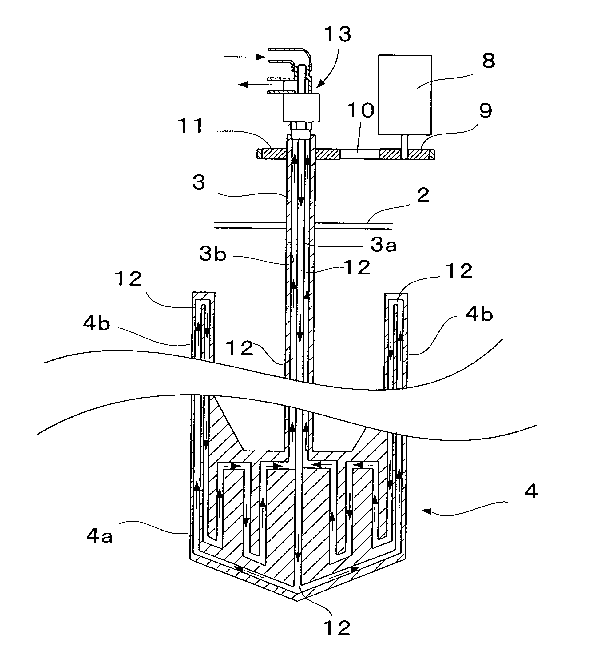
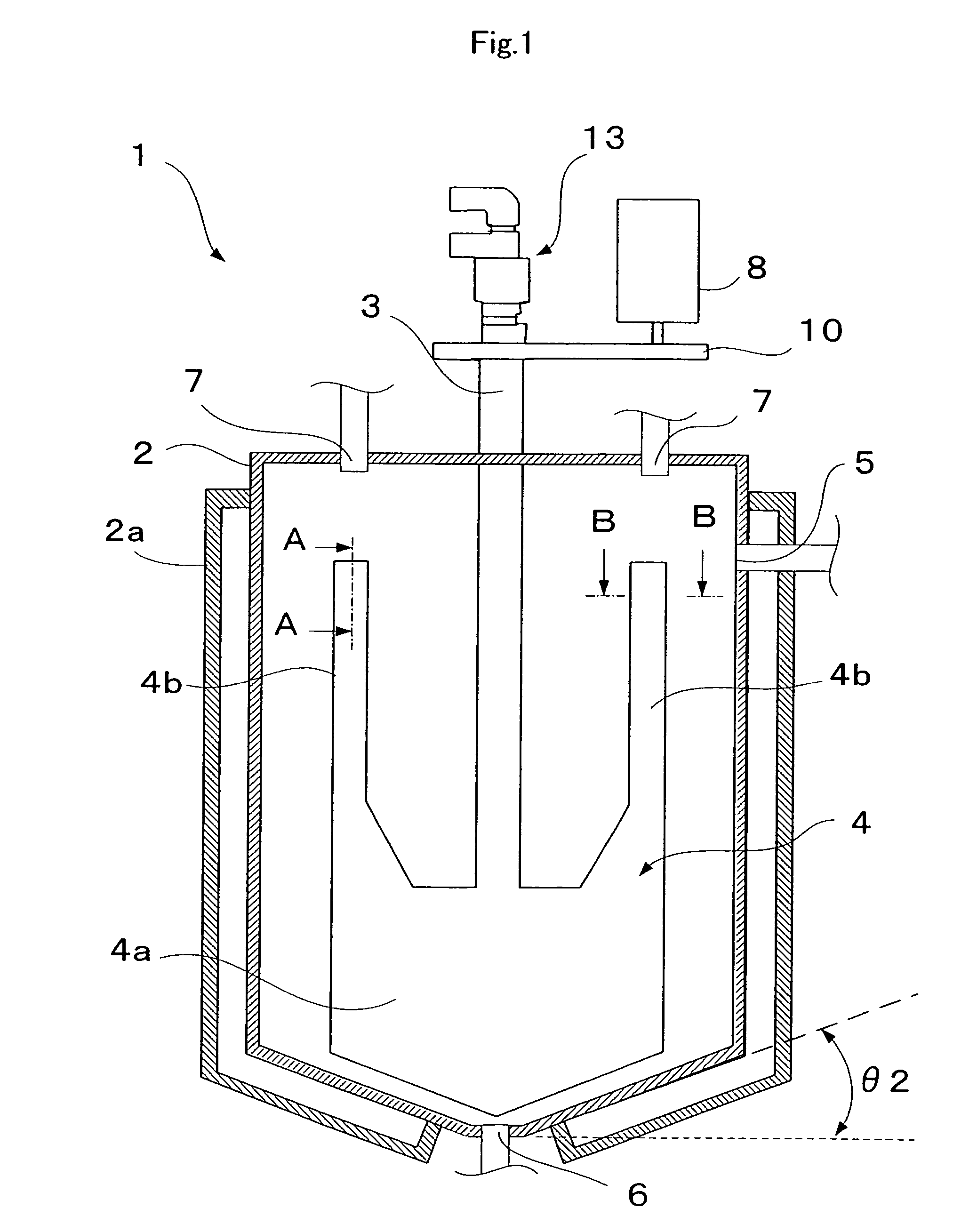
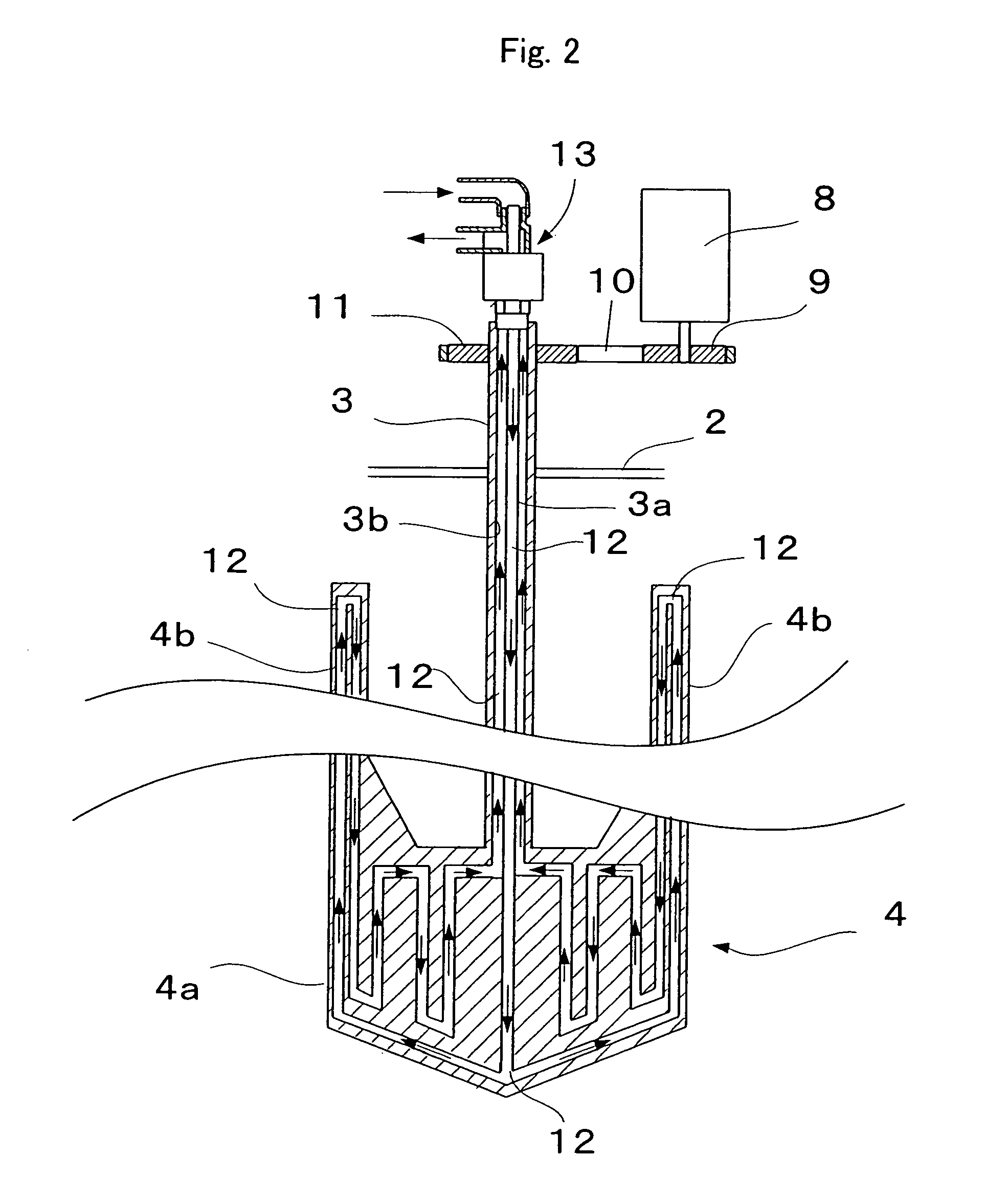
[0049]an agitator will be described with reference to FIGS. 1-3 below. FIG. 1 is a longitudinal sectional view showing the inner structure of the agitator, and FIG. 2 is a partial longitudinal sectional view showing the inner structure of the flat paddle blade part of FIG. 1.

[0050]The agitator 1 comprises an agitating vessel 2; a rotating shaft 3 extending vertically in the inner center of the agitating vessel 2; and a flat paddle blade 4 as an agitating blade mounted on the rotating shaft 3.

[0051]The agitating vessel 2 comprises a fluid inlet 5 in an upper part thereof and a fluid outlet 6 at the bottom. It has a cylindrical circumferential side face and a coolant jacket 2a therearound.

[0052]The coolant jacket can be of a known constitution, and allows a coolant medium such as a coolant water to circulate inside. In one embodiment, the configuration of the bottom of the agitating vessel 2 is a truncated cone with the narrow portion downwards. Moreover, the agitating vessel 2 compri...

second embodiment

[0065]In a second embodiment, the flat paddle blade 4 has, as shown in the cross sectional configurations of FIGS. 4 and 5, a peripheral portion which is entirely tapered by inclined surfaces 4c, 4c formed two sides and has a V-shaped cross sectional configuration. In the examples shown in FIGS. 4 and 5, the inclined surfaces 4c, 4c are flat surfaces, but they can also be formed by curving faces as shown in the cross-sectional view of FIG. 6. Moreover, the tip tapered by the inclined surfaces 4c, 4c, is illustrated as a sharp point in the examples shown in FIGS. 4 and 5, but can be, for example, of rounded U-shaped cross sectional configuration shown in FIG. 6. It should be noted that the cross sectional configuration of only the upper flat paddle blade portion 4b is shown in FIGS. 4-6, but the case for the bottom flat paddle blade portion 4a is also the same.

[0066]In one embodiment, the agitators of the aforementioned first and second embodiments are mainly used to be incorporated ...


PUM


Abstract

An agitator able to mix and disperse a variety of fluids of various fluid volumes with different viscosities ranging from low to high, and having excellent, cleanability and improved cooling efficiency is provided. The agitator comprises a rotating shaft 3 extending vertically inside an agitating vessel 2, and a flat paddle blade 4 mounted on the rotating shaft 3. The flat paddle blade has a bottom flat paddle blade portion 4a extending outwards from the bottom of the rotating shaft 3 and a rectangular upper flat paddle blade portion 4b extending upward from an upper part of each side end of the bottom flat paddle blade portion 4a. The dimensional ratio (b / a) of the blade diameter (b) of the bottom flat paddle blade portion 4a to the inner diameter (a) of the agitating vessel 2 is from 0.6 to 0.9, and the dimensional ratio (d / c) of the height (d) of an upper flat paddle blade portion 4b to the height (c) of the bottom flat paddle blade portion 4a is from 1 to 4. A passage 12 is formed inside the rotating shaft 3 and flat paddle blade 4 for passing a coolant medium therethrough.

Description

TECHNICAL FIELD[0001]The present invention relates to an agitator, a circulatory cleaning device attached to the agitator, and a circulatory line system comprising the circulatory cleaning device.BACKGROUND ART[0002]Conventionally, coating compositions, inks and like coloring liquids are clear varnishes containing pigment pastes. Pigment pastes are generally prepared by the steps of mixing pigments, resins, organic solvents, and like raw materials in an agitator to prepare a mill base, and then passing this mill base a few times through a bead mill dispersion apparatus or like continuous dispersion apparatus to disperse the pigment.[0003]Specifically, the commonly employed pigment dispersion method comprises the steps of feeding an unprocessed pigment paste stored in a feeding vessel to a dispersion apparatus, temporarily storing the pigment paste obtained by dispersing it in the dispersion apparatus in a receiving vessel, returning the pigment paste stored in the receiving vessel t...

Claims


Application Information

Patent Timeline
Patent Type & Authority Patents(United States)
IPC IPC(8): B01F7/20B01F27/906B08B3/02
CPCB01F5/104B01F7/0015B01F7/18B01F7/20B01F13/1047B01F15/00032B01F15/065B01F15/068B01F7/00116B01F7/00141B01F7/00266B01F7/00291B01F2015/061B01F25/52B01F27/0721B01F27/0724B01F27/0725B01F27/1122B01F27/1125B01F27/906B01F27/90B01F33/831B01F35/1453B01F2035/98B01F35/95B01F35/92
Inventor MATSUMOTO, HIROYUKIKURAMOTO, MUTSUOHIRAKI, MASAHIKO
Owner KANSAI PAINT CO LTD
Why Eureka
Try Eureka