Oven muffle

Inactive Publication Date: 2009-12-10
SCHOTT AG
View PDF17 Cites 13 Cited by
  • Summary
  • Abstract
  • Description
  • Claims
  • Application Information

AI Technical Summary

Benefits of technology

[0019]The structural elements can be produced for a low production cost if the structural elements are formed onto the wall element and are of one piece with it.
[0020]An oven muffle according to this invention is preferably equipped so that a heating element is positioned outside the receiving space, in the region of or near the outer surface of at least one of the wall elements. This further improves the cleanability of the interi

Problems solved by technology

A coating on the muffle interior would be susceptible to scratching and there would also be the prob

Method used


Image

  • Oven muffle
  • Oven muffle
  • Oven muffle

Examples


Embodiment Construction

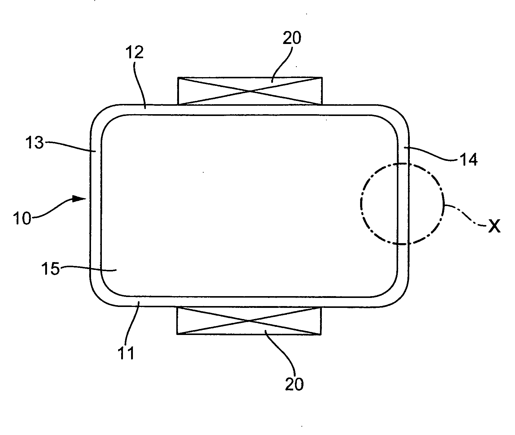
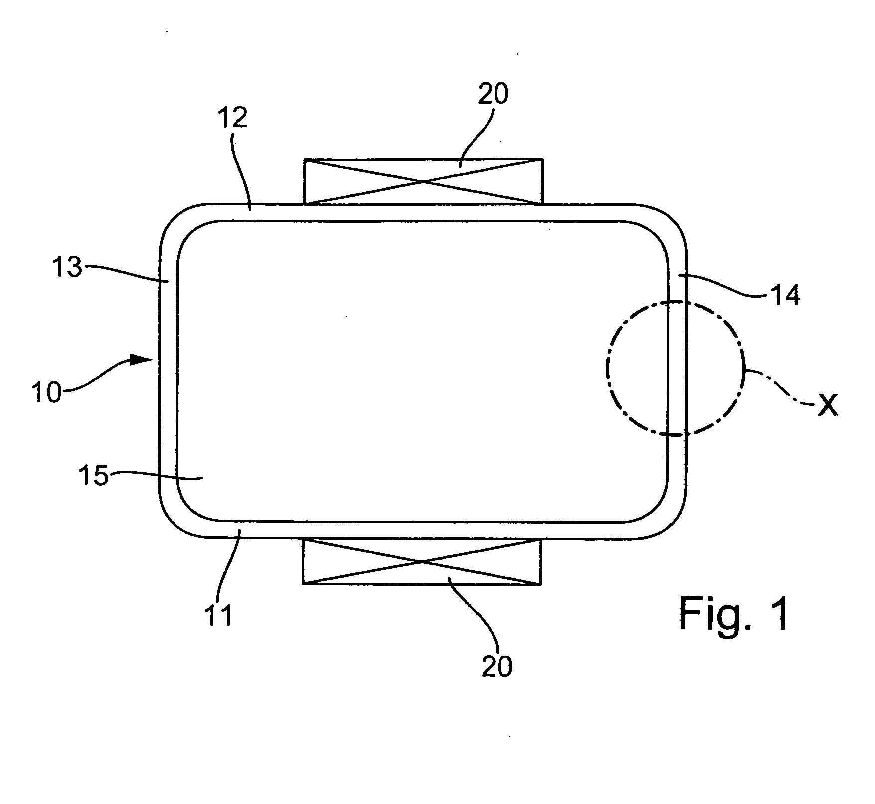
[0025]FIG. 1 shows an oven muffle that encloses an interior, which serves as a cooking space. The interior is delimited by five wall elements 11-15, a bottom wall element 11, a top wall element 12, two vertical side wall elements, and one rear wall element 15. Outside of the interior, a respective heating element 20 is positioned or situated on the outer surface of the bottom wall element 11 and the outer surface of the top element 12. The heating elements 20 are preferably composed of or are of halogen heating elements. It is also possible to use halogen lamps and normal resistance wire to produce different wavelengths. Another option is to use inexpensive strip heaters of the type employed in glass ceramic cook tops. In addition, heating elements 20 can be provided behind the side wall elements 13, 14 and / or the rear wall element 15 to improve energy distribution in the interior of the oven muffle. This embodiment has an advantage that with a stacked arrangement of several baking ...


PUM


Abstract

An oven muffle having a receiving space, at least some regions of which are delimited by wall elements, in which at least one of the wall elements is permeable to IR radiation or has a region that is permeable to IR radiation. In the oven muffle, the cooking performance is successfully improved while also providing an easily cleanable interior because a reflecting element that reflects IR radiation is positioned in the region of the outer surface of the wall element on a side oriented away from the receiving space.

Description

BACKGROUND OF THE INVENTION[0001]1. Field of the Invention[0002]This invention relates to an oven muffle having a receiving space, at least some regions of which are delimited by wall elements, in which at least one of the wall elements is permeable to IR radiation or has a region that is permeable to IR radiation.[0003]2. Discussion of Related Art[0004]Electrically heated ovens for freestanding ranges or for installation in a kitchen unit are known and essentially include an enameled oven muffle, which is heated from above and below with tubular heating elements. On the front side, the oven muffle is closed by a framed glass door. Usually, the upper heating system is positioned on the interior of the oven muffle and in high-end ovens, is also assisted by a second heating element that enables the oven to execute a grilling function. The lower heating element is attached to the outside of the muffle floor. In addition to these standard heating schemes for upper / lower heating and gril...

Claims


Application Information

Patent Timeline
IPC IPC(8): A21B1/00
CPCF24C15/08F24C7/06
Inventor TAPLAN, MARTINZENKER, THOMASSCHMIDBAUER, WOLFGANGBACKES, SASCHAGOETZ, HELGA
Owner SCHOTT AG
Why Eureka
Try Eureka