Propeller Shaft and Constant-Velocity Joint Used in Said Propeller Shaft

a technology of constant velocity joint and propeller shaft, which is applied in the direction of yielding coupling, rotary machine parts, vehicle components, etc., can solve the problems of increasing the weight and achieve the effect of securing the strength of the constant velocity joint and suppressing the weight increas

Active Publication Date: 2017-01-19
HITACHI ASTEMO LTD
View PDF3 Cites 7 Cited by
  • Summary
  • Abstract
  • Description
  • Claims
  • Application Information

AI Technical Summary

Benefits of technology

[0007]According to the above present invention, it is possible to suppress

Problems solved by technology

The formation of the engagement groove requires that the member is thickened in order to get strength of

Method used


Image

  • Propeller Shaft and Constant-Velocity Joint Used in Said Propeller Shaft
  • Propeller Shaft and Constant-Velocity Joint Used in Said Propeller Shaft
  • Propeller Shaft and Constant-Velocity Joint Used in Said Propeller Shaft

Examples


first embodiment

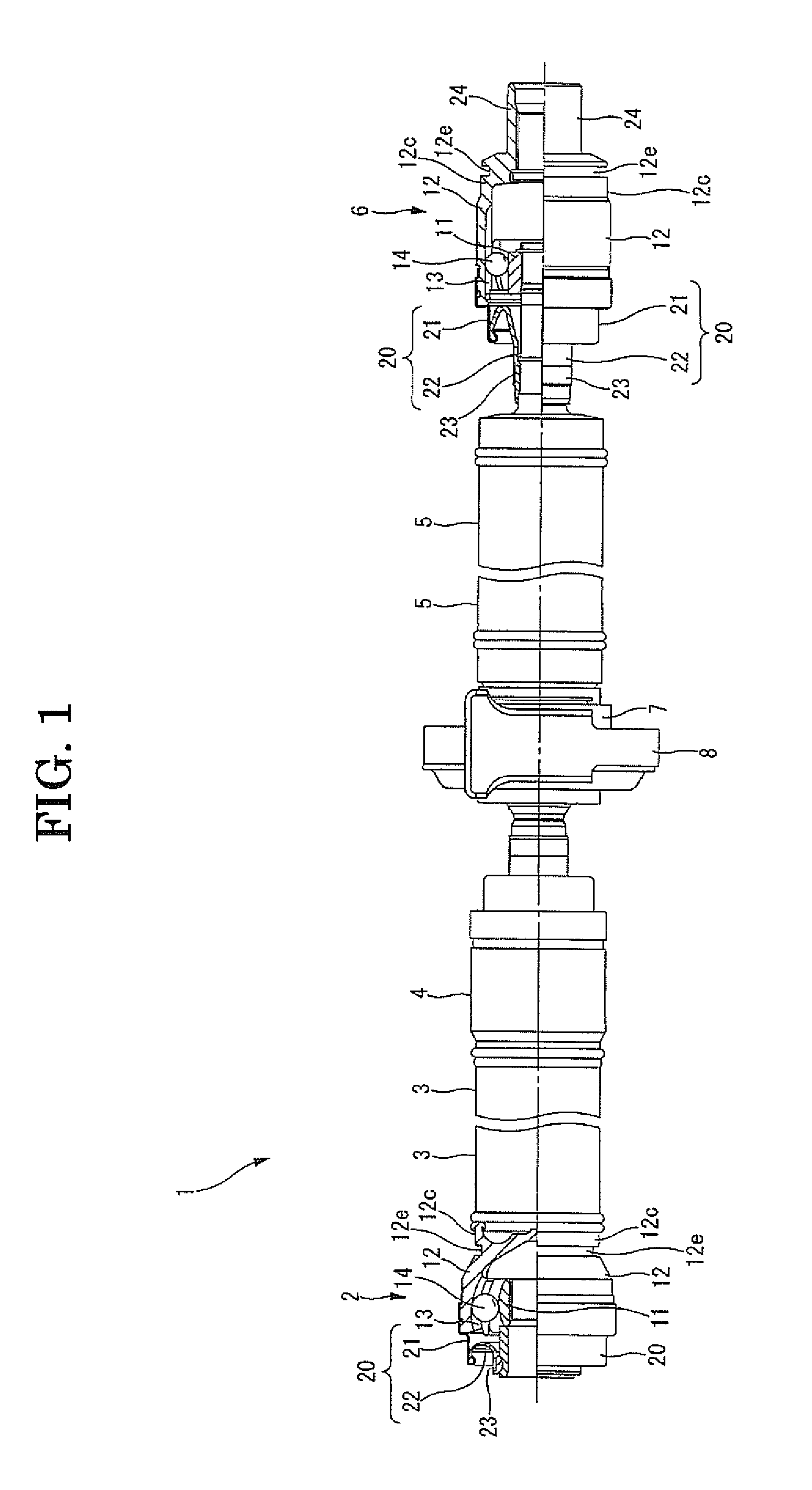
[0021]A constant-velocity joint in the first embodiment of the present invention will be explained with reference to FIG. 1 to FIG. 4. This mode is what is applied to a propeller shaft for a vehicle.

[0022]As shown in FIG. 1, a propeller shaft 1 is equipped with a drive shaft 3 linked to an input shaft (not shown), which is connected to a transmission, through a first constant-velocity joint 2; a driven shaft 5 linked to the drive shaft 3 through a second constant-velocity joint 4; an output shaft (not shown) being in a differential gear side and linked to the driven shaft 5 through a third constant-velocity joint 6; and a center bearing 7 supported to a car body (not shown) through a bracket 8 installed near the second constant-velocity joint 4. The drive shaft 3 and the driven shaft 5 are made of aluminum alloy. The input shaft and the output shaft are made of iron-based metal.

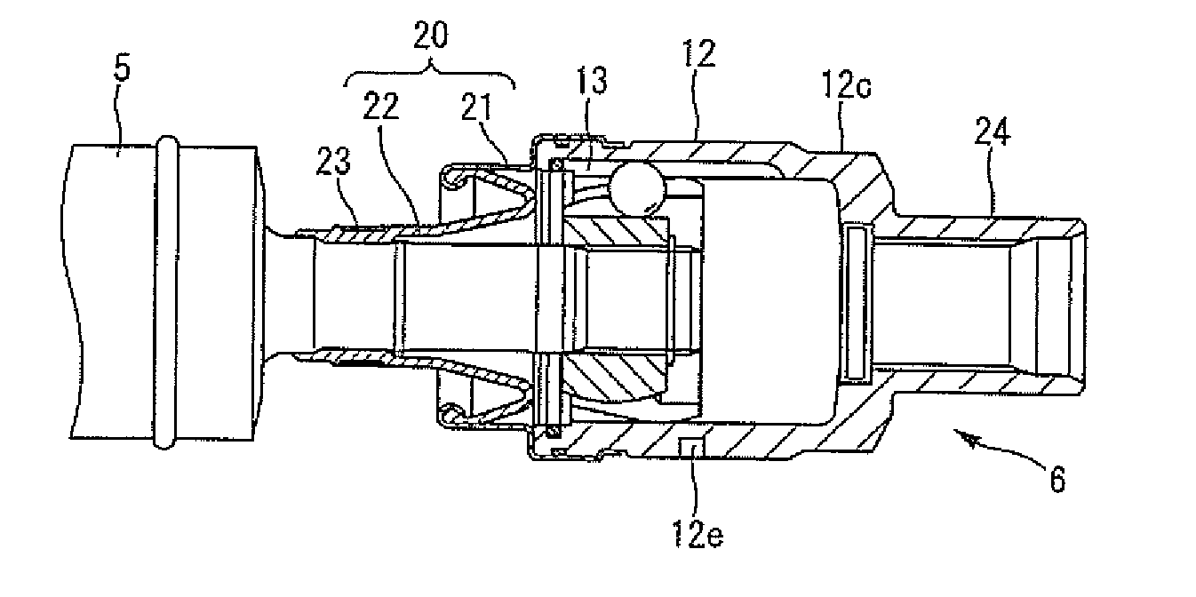
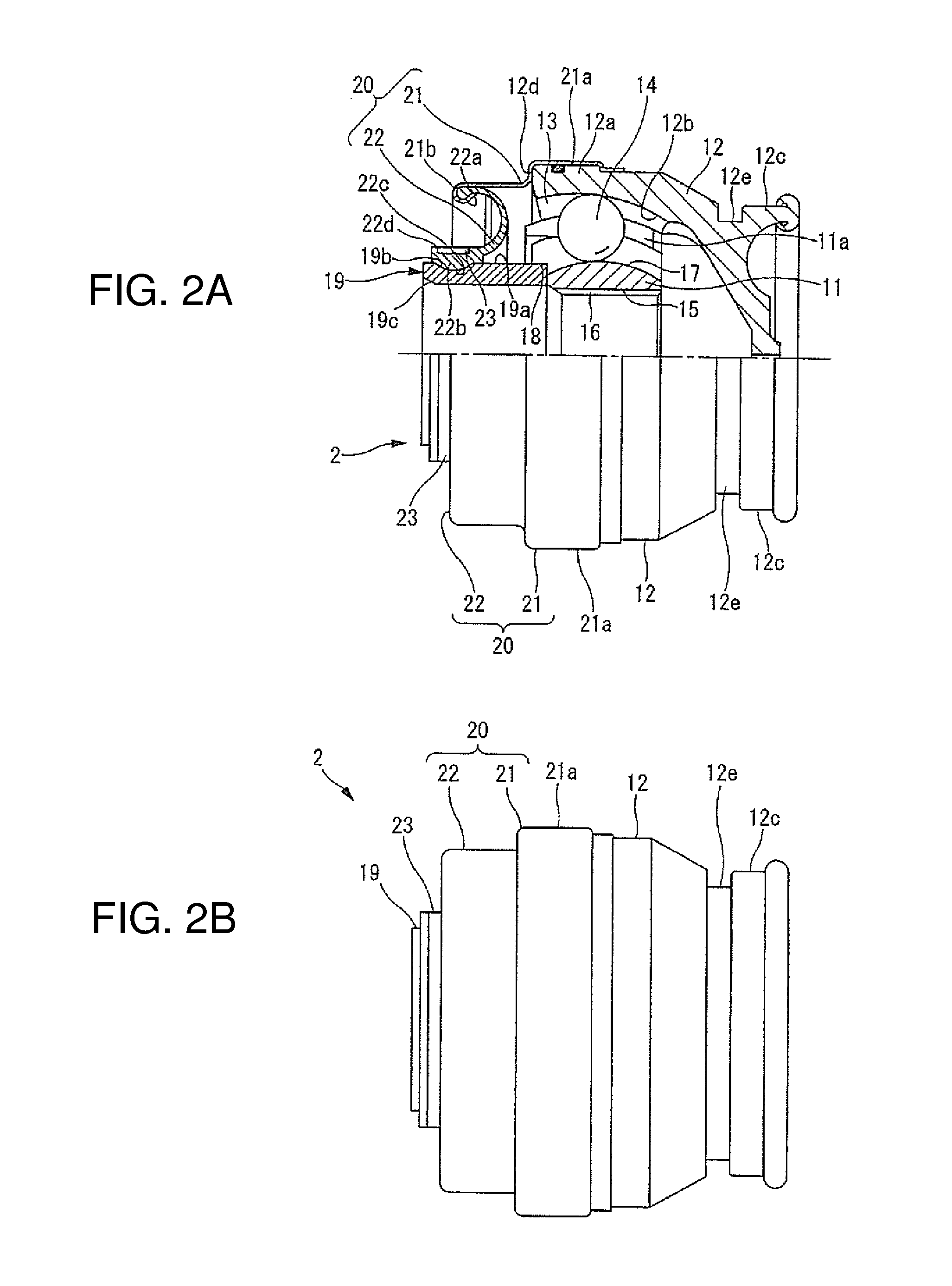
[0023]As shown in FIG. 2, the first constant-velocity joint 2 is equipped with an inner ring member 11 get...

second embodiment

[0047]The third constant-velocity joint 6 in the second embodiment shown in FIG. 5 has the same structure as that of the third constant-velocity joint 6 in the first embodiment except that the engagement grooves 12e, which function as locking parts where the engagement member engages, are partially formed in the circumferential direction at the position avoiding the raceway grooves 13 in the axial direction of the outside wall of the outer ring member 12 in the minimum diameter part 12c of the outer ring member 12.

[0048]In this embodiment, it is obvious that the same effects of the first constant-velocity joint 2 in the first embodiment can be obtained. Especially, as the engagement grooves 12e are partially formed in the circumferential direction of the outside wall of the outer ring member 12, the third constant-velocity joint 6 is lightened. Furthermore, as the engagement grooves 12e are partially formed in the range avoiding the positions corresponding to the raceway grooves 13 ...

third embodiment

[0049]The third constant-velocity joint 6 in the third embodiment shown in FIG. 6 also has a structure that the engagement grooves 12e, which function as locking parts where teeth of the engagement member engage wherein the teeth are eight-teeth type and are applied in assembling or dismantling the propeller shaft 1, are partially formed in the circumferential direction in the range avoiding the positions corresponding to the raceway grooves 13 in the axial direction of the outside wall of the outer ring member 12.

[0050]Especially, the engagement grooves 12e are smaller than those of the second embodiment. Although the engagement grooves 12e are arranged near to the boot member 20 in the outside wall of the outer ring member 12, it may be arranged in the minimum diameter part 12c of the outer ring member like that of the second embodiment.

[0051]According to this mode, a plurality of the engagement grooves 12e is formed in the range avoiding the positions corresponding to the raceway...


PUM


Abstract

The first constant-velocity joint has an inner ring member, an outer ring member housing the inner ring member, and balls, which are installed in raceway grooves formed at prescribed intervals in a circumferential direction in the outer ring member and which extend along an axial direction, for transmitting rotational torque between the inner ring member and the outer ring member. Furthermore, the constant-velocity joint is formed so that one of the inner ring member and the outer ring member connects to an attaching member installed to a vehicle side with a spline, and so that the other of them connects to a power transmission shaft. In outside wall of the outer ring member, an engagement groove is formed so as to engage with an engagement member applied to connection or release thereof in a range avoiding positions corresponding to the raceway grooves in an axial direction or a circumferential direction.

Description

TECHNICAL FIELD[0001]The present invention relates to, for instance, a propeller shaft for an automobile and a constant-velocity joint used in the propeller shaft.BACKGROUND ART[0002]The propeller shaft is generally divided into two or three by a drive shaft which is connected to a vehicle side (transmission side) and a driven shaft which is connected to a differential gear side. Furthermore, with joint structures such as a cardan joint, a constant-velocity joint (for example, Patent Document 1), etc. installed in opposite ends of the divisions, the propeller shaft is rotatably supported by support equipment which is installed almost in the center of an axial direction.PRIOR ART DOCUMENTPatent Document[0003]Patent Document 1: Japanese Patent Application Publication 2011-225153SUMMARY OF THE INVENTION[0004]In a conventional constant-velocity joint, an engagement groove is formed at a position which overlaps with a raceway groove of an outer ring member. The engagement groove engages ...

Claims


Application Information

Patent Timeline
IPC IPC(8): F16D3/223F16D1/06
CPCF16D3/223F16D2003/22326F16D1/06Y10S464/906B60B35/128
Inventor SUGIYAMA, KENICHIMABE, YASUTOMOMASUDA, TOSHIYUKIKOMAI, HIROMICHI
Owner HITACHI ASTEMO LTD
Why Eureka
Try Eureka