Front device

a front device and box body technology, applied in the direction of buildings, buildings, constructions, etc., can solve the problems of reducing operation efficiency, difficult to obtain satisfactory strength near the boss, and limiting the strength of the box body as a whole, so as to improve durability, and reduce the weight of the box body.

Inactive Publication Date: 2007-06-07
NIHON KENKI CO LTD
View PDF3 Cites 7 Cited by
  • Summary
  • Abstract
  • Description
  • Claims
  • Application Information

AI Technical Summary

Benefits of technology

[0010] In the view of the above described problems with the prior art, it is an object of the present invention to provide a front device that can suppress an increase in the weight of a box member, can easily improve the strength of the box member in the vicinity of a boss, and can improve durability.

Problems solved by technology

The rib can increase the flexural strength of the left web, but there is a limit to greatly increasing the strength of the box member as a whole.
Thus, there is a problem that it is difficult for a satisfactory strength to be obtained near the boss.
However, when thick steel plates are simply employed, the weight of the boom is increased, which causes problems, i.e., an increase in the size of an actuator that drives the boom and results in the reduction of the operation efficiency.
In addition, even when the blocking plate is provided inside of the box member, the strength may be insufficient near the boss because this blocking plate is located separate from the boss.

Method used


Image

  • Front device
  • Front device
  • Front device

Examples


first embodiment

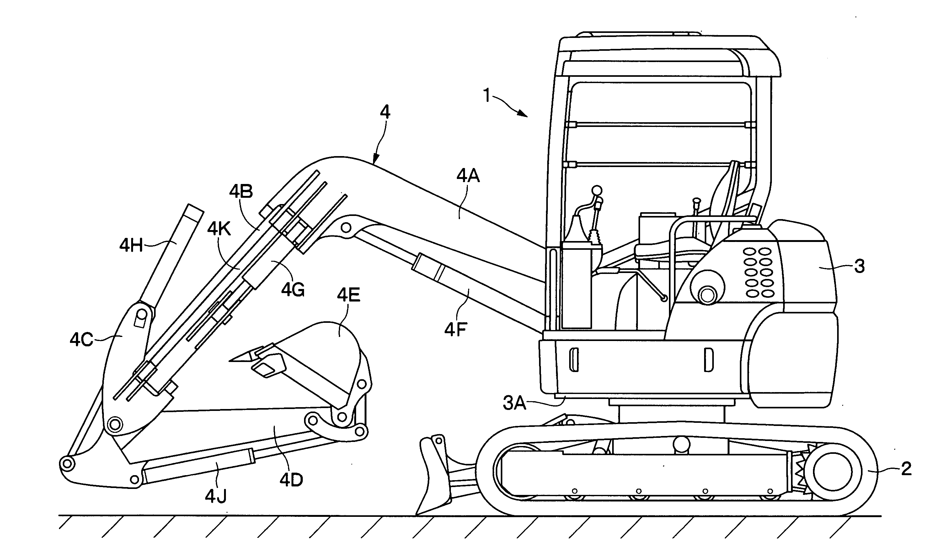
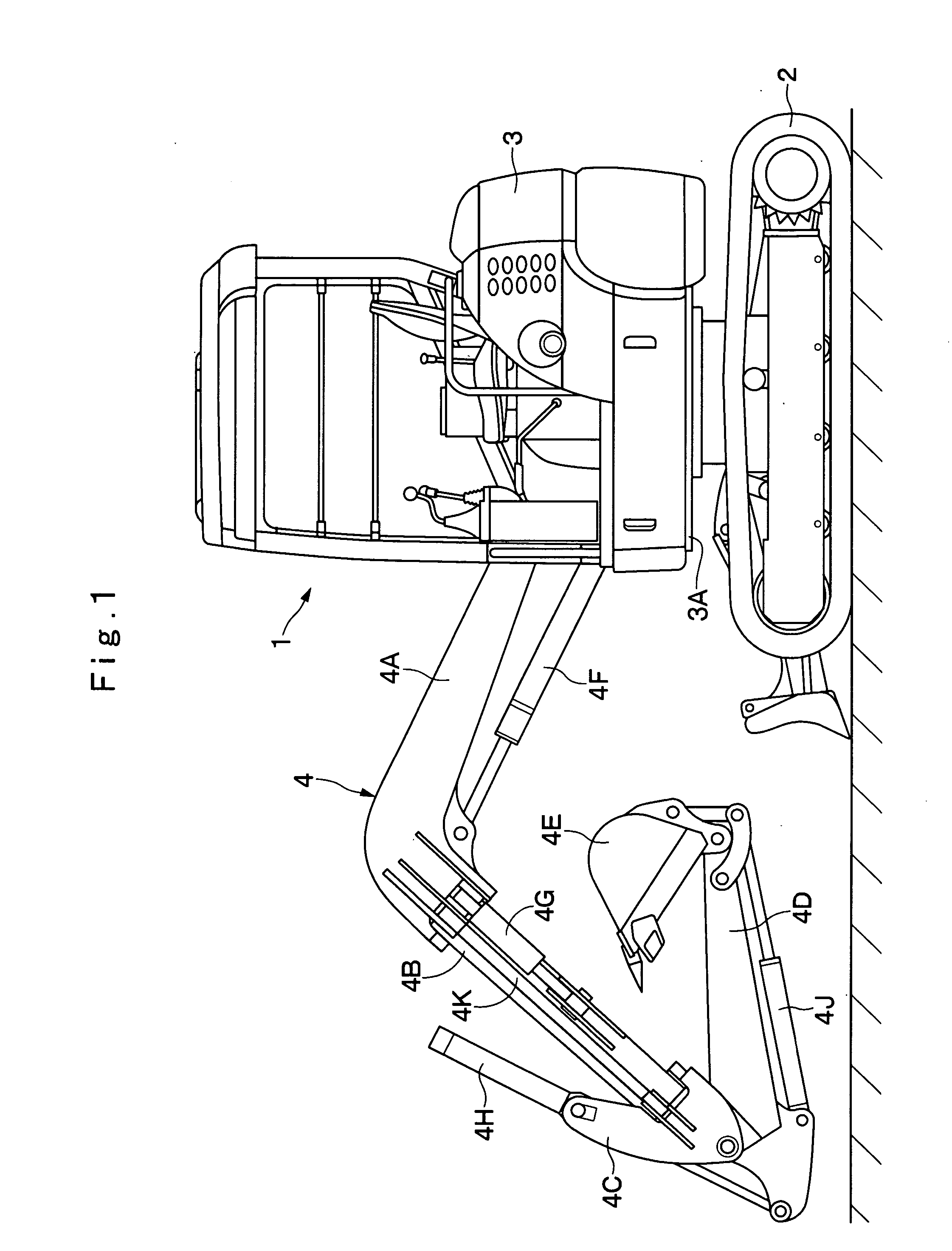
[0050] In the drawings, indicated at 1 is a hydraulic excavator of an offset boom type applied for the The hydraulic excavator 1 is roughly constituted by a vehicular lower structure 2, an upper revolving structure 3 which is rotatably mounted on the vehicular lower structure 2, and a working mechanism 4, which will be described later, that is liftably attached to the front of the upper revolving structure 3 for performing the excavation of dirt, etc. Further, the vehicular lower structure 2 and the upper revolving structure 3 constitute the body of the hydraulic excavator 1.

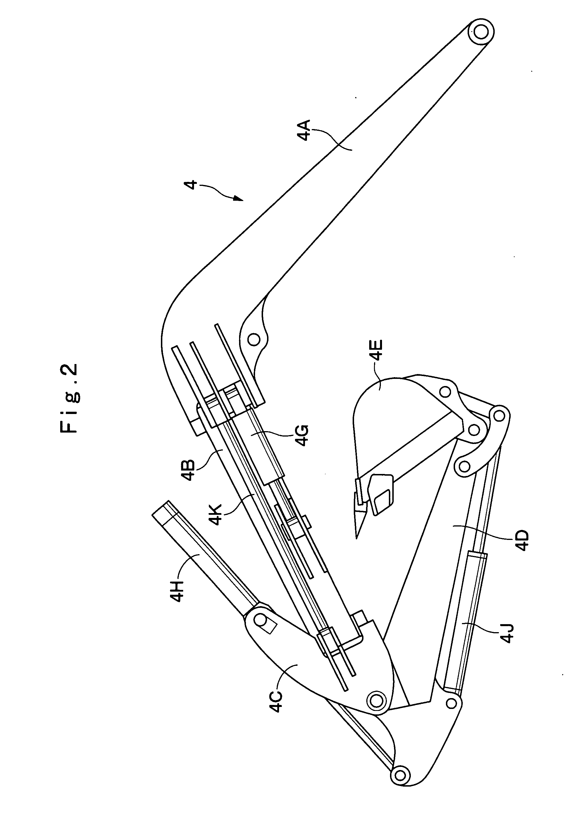
[0051] Denoted at 4 is a working mechanism of an offset boom type, and this working mechanism 4 is liftably attached to the upper revolving structure 3. As shown in FIGS. 1 and 2, the working mechanism 4 is constituted by a lower boom 4A which is liftably coupled to the upper revolving structure 3, an upper boom 4B which is swingably coupled to the distal end of the lower boom 4A for swinging movements in leftw...

third embodiment

[0107] The upper flange 53, the lower flange 54, the left web 55 and the right web 56 are formed of steel plates, both ends of which are bent. In this case, substantially in the same manner as the third embodiment, the upper flange 53 is constituted by an upper face plate portion 53A and bent plate portions-53B, 53C, while the lower flange 54 is constituted by a lower face plate portion 54A and bent plate portions 54B, 54C.

[0108] Furthermore, similarly to the first embodiment, the left web 55 is constituted by a side face plate portion 55A and bent plate portions 55B, 55C, while the right web 56 is constituted by a side face plate portion 56A and bent plate portions 56B, 56C. Brackets 54D, 55D of offset cylinders are securely fixed respectively to the lower flange 54 and the left web 55.

[0109] Middle portion of the box member 52 is formed like a square column by welding together the upper face plate portion 53A, the lower face plate portion 54A, the left side face plate portion 55A...

fifth embodiment

[0118] The fifth embodiment for a front device according to the present invention is shown in FIG. 19. The characteristic of this embodiment is applied for the lower boom of a working mechanism of an offset boom type.

[0119] Indicated at 71 is a lower boom that serves as a front device. The lower boom 71 is used as a lower boom 4A (see FIGS. 1 and 2) of a working mechanism 4 of an offset boom type. In this case, the lower boom 71 is, for example, an elongated hollow structure having the shape of a box in transverse cross section and having a curved distal end, and is extended in the front and the rear directions of a vehicle body. Further, the lower boom 71 is constituted by a box member 72, a vehicle body boss 77 and reinforcement plates 78, 79 that will be described later.

[0120] Indicated at 72 is a box member that serves as the main body of the lower boom 71. Substantially in the same manner as the first embodiment, the box member 72 is formed like a square column as a whole by w...


PUM


Abstract

An upper boom is constituted by a box member having a shape like a box that includes an upper flange, a lower flange, a left web and a right web, and bosses that are welded to both ends of the box member. Bent plate portions which are bent inward are provided at both ends of the left web, and bent plate portions are also provided at both ends of the right web. Reinforcement plates are positioned at an outside of the bent plate portions and welded between the left web and the boss, and reinforcement plates are also welded between the right web and the boss at an outside of the bent plate portions. With these bent plate portions and the reinforcement plates, a double structure can be provided in the vicinities of the bosses, and these portions can be reinforced.

Description

TECHNICAL FIELD [0001] This invention relates to a front device that is mounted on a construction machine, such as a hydraulic excavator or a hydraulic crane, and is appropriately employed, for example, as a boom or an arm for a working mechanism. BACKGROUND ART [0002] Generally, for a construction machine such as a hydraulic excavator or a hydraulic crane, a working mechanism for performing excavating or loading, for example, is liftably provided. As such a working mechanism, a hydraulic excavator that includes a front device such as a boom or an arm is well known (e.g., see Japanese Patent Laid-Open No. 2001-81810). [0003] Consider the boom of a hydraulic excavator as an example of a front device according to this first prior art. This boom includes a box member, which is formed as a hollow structure having the shape of a box by welding together an upper flange, a lower flange, a left web and a right web, and a boss which is located on the base end of the box member, and is liftab...

Claims


Application Information

Patent Timeline
Patent Type & Authority Applications(United States)
IPC IPC(8): E02F3/36E02F3/38
CPCE02F3/301E02F3/307E02F3/38
Inventor ISHIKAWA, HIRONAOKISHIMOTO, SHINGO
Owner NIHON KENKI CO LTD
Why Eureka
Try Eureka