Device and method for controlling prime mover

a technology of prime mover and control apparatus, which is applied in the direction of electric devices, machines/engines, propulsion parts, etc., can solve the problems of rotating shaft vibration of the motor, and achieve the effect of preventing potential vibration of the driving system

Inactive Publication Date: 2006-08-10
TOYOTA JIDOSHA KK
View PDF23 Cites 20 Cited by
  • Summary
  • Abstract
  • Description
  • Claims
  • Application Information

AI Technical Summary

Benefits of technology

[0004] The motor control apparatus and the corresponding motor control method of the invention aim to prevent potential vibrations of a driving system in the course of skid control.

Problems solved by technology

In the prior art motor control apparatus, however, restoration of the restricted output torque level may cause vibrations of a rotating shaft of the motor (vibrations of a driving system).

Method used


Image

  • Device and method for controlling prime mover
  • Device and method for controlling prime mover
  • Device and method for controlling prime mover

Examples


Embodiment Construction

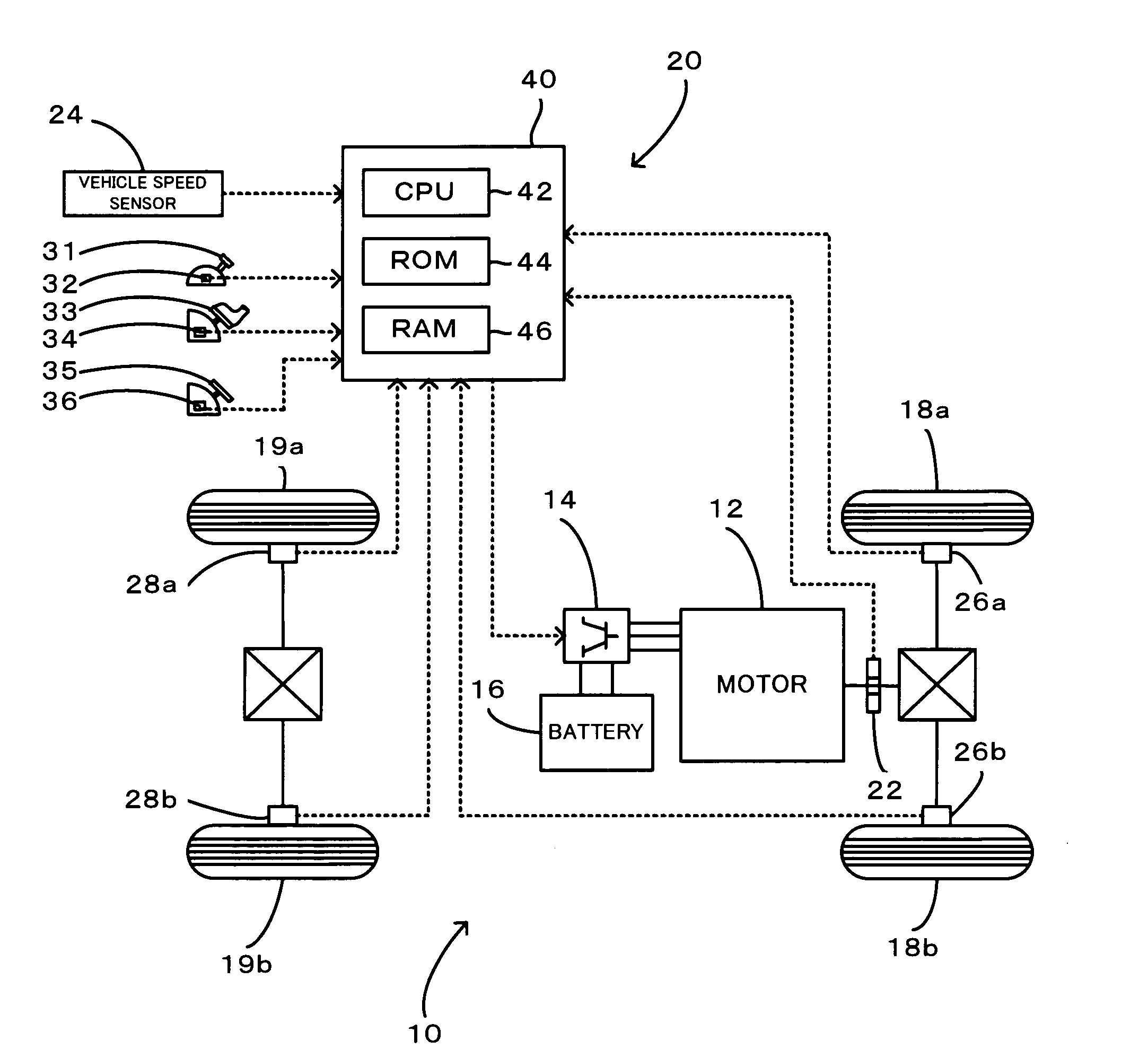
[0037] Some modes of carrying out the invention are described below as preferred embodiments. FIG. 1 schematically illustrates the configuration of an electric vehicle 10 equipped with a motor control apparatus 20 in one embodiment of the invention. As illustrated, the motor control apparatus 20 of the embodiment is constructed to drive and control a motor 12, which uses electric power supplied from a battery 16 via an inverter circuit 14 and outputs power to a drive shaft linked to drive wheels 18a, 18b of the electric vehicle 10. The motor control apparatus 20 includes a rotation angle sensor 22 that measures a rotation angle θ of a rotating shaft of the motor 12, a vehicle speed sensor 24 that measures a driving speed of the vehicle 10, wheel speed sensors 26a, 26b, 28a, and 28b that respectively measure wheel speeds of the drive wheels (front wheels) 18a and 18b and driven wheels (rear wheels) 19a and 19b driven by the drive wheels 18a and 18b, diversity of sensors that detect t...


PUM


Abstract

An increase in angular acceleration α of a rotating shaft of a motor, which outputs a torque to a drive shaft linked to drive wheels, may cause a skid on the drive wheels. In response to detection of a skid, the control procedure of the invention sets a maximum torque Tmax according to a preset map representing a relation between the angular acceleration α and the maximum torque Tmax, and restricts an output torque level to the drive shaft. The map is set to decrease the maximum torque Tmax with an in crease in angular acceleration α. The restricted output torque level is restored at a zero cross timing of the angular acceleration α after a negative peak in the course of convergence of the skid. This arrangement makes the direction of the torque restored from the torque restriction identical with the direction of the angular acceleration, thus effectively reducing torsions of the drive shaft and thereby preventing potential torsional vibrations of the drive shaft.

Description

TECHNICAL FIELD [0001] The present invention relates to a motor control apparatus and a motor control method. More specifically the invention pertains to a motor control apparatus that controls a motor, which is mounted on a vehicle and outputs power to a drive shaft linked to drive wheels, as well as to a corresponding motor control method. BACKGROUND ART [0002] One proposed motor control apparatus of controlling a motor mounted on a vehicle restricts an output torque level from the motor to a drive shaft, in response to detection of wheelspin of drive wheels caused by the torque output from the motor (see, for example, Japanese Patent Laid-Open Gazette No. 2001-295676). This known motor control apparatus detects the occurrence of a skid in response to an increase in angular acceleration of the drive wheels (that is, a time variation of angular velocity) over a predetermined threshold value and lowers the output torque level from the motor. The restricted output torque level from t...

Claims


Application Information

Patent Timeline
Patent Type & Authority Applications(United States)
IPC IPC(8): H02P7/00B60K6/445B60K6/448B60K6/485B60L3/10B60L15/20B60W10/00B60W10/06B60W20/00B60W20/10F02D29/02
CPCB60L3/102B60L3/106B60L2200/26F02D29/02Y02T10/7283B60L15/2045B60L2270/145Y02T10/64Y02T10/72B60L15/20
Inventor HOMMI, AKIRAHAMAJIMA, KIYOTAKANADA, MITSUHIRO
Owner TOYOTA JIDOSHA KK
Why Eureka
Try Eureka