Cloth covered instrument panel

a cloth or fabric instrument panel technology, applied in the direction of instruments, process and machine control, mechanical control devices, etc., can solve the problems of inability to provide multiple colors, textures and/or materials, and inability to provide cloth or fabric instrument panels. to achieve the effect of reducing the number of instruments, increasing the complexity of the task, and increasing the difficulty of assembly

Inactive Publication Date: 2006-08-10
COLLINS & AIKMAN PROD CO
View PDF48 Cites 13 Cited by
  • Summary
  • Abstract
  • Description
  • Claims
  • Application Information

AI Technical Summary

Benefits of technology

[0030] It is a further object of the present invention to provide novel processes for joining these multiple materials together to form a high quality, aesthetically pleasing joint line having a consistent but minimal gap between adjoining surfaces.

Problems solved by technology

While it is well known to use multiple materials to cover vertical trim panels, such as door panels, etc., due to the more complex shapes and weathering requirements for instrument panels, which are essentially horizontally disposed and exposed to heavy sunloads through the windshield, cloth covered instrument panels have not been available nor acceptable.
Further, to provide an instrument panel having multiple colors, textures and / or materials, one of which is a cloth or fabric, is an even more complex task.
This type of infold joint may not be acceptable for an instrument panel as a more uniform joint line having a small gap may be required for a panel directly in full and constant view of the occupants.
Further, this type of joint may not provide the reliability of fracture required for an air bag door tear seam.
While all of these references deal with joining sheets of material together, they do not address the need to provide a high quality joint line having a consistent but minimal gap and having a definable tear strength, using cloth materials for an instrument panel application.

Method used


Image

  • Cloth covered instrument panel
  • Cloth covered instrument panel
  • Cloth covered instrument panel

Examples


Embodiment Construction

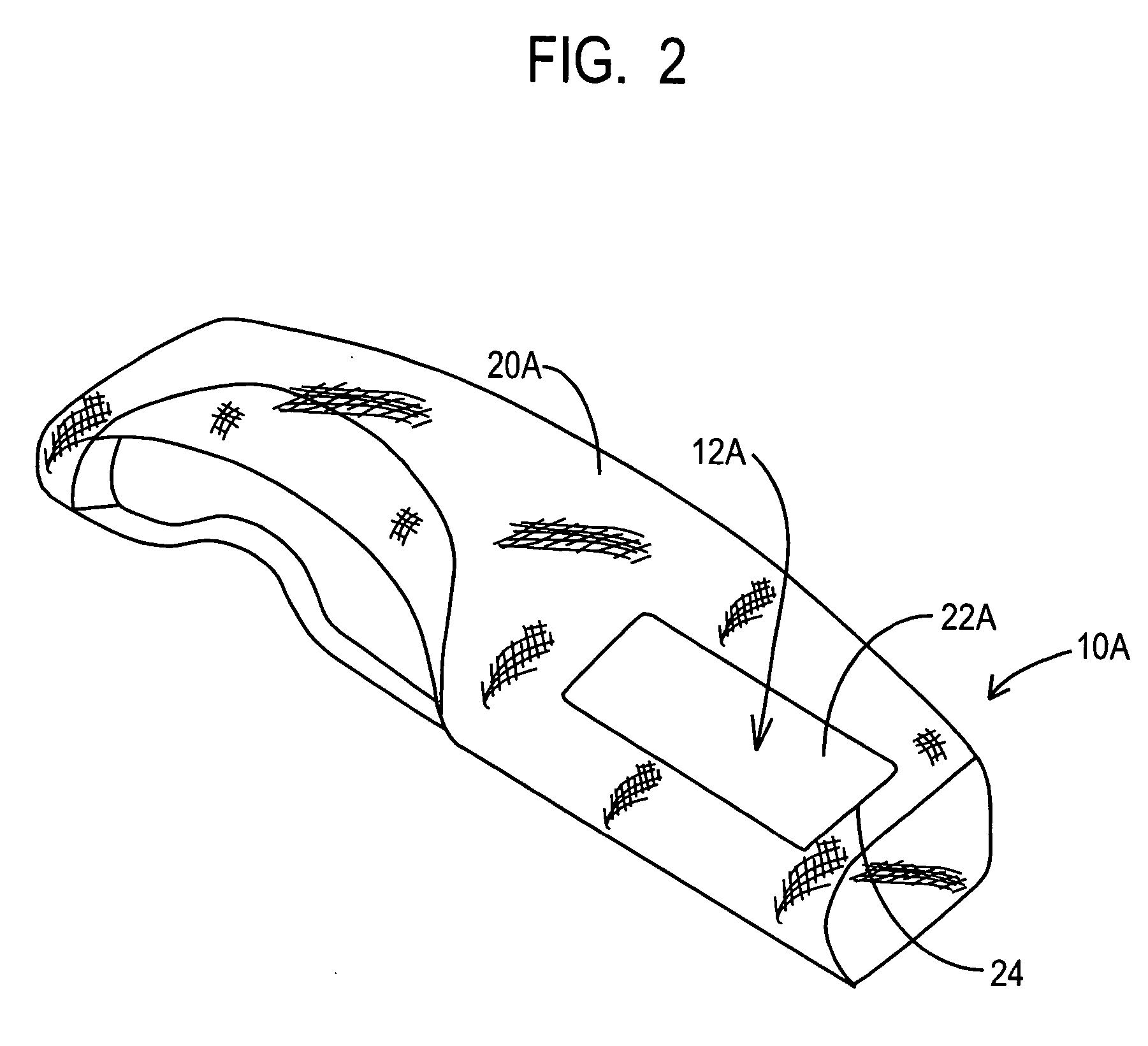
[0037] For elements common to various embodiments of the present invention, the numeral reference character between the embodiments is held constant, but distinguished by the addition of an alphanumeric character to the existing numerical reference character. In other words, for example, an element referenced at 10 in the first embodiment is correspondingly referenced at 10A, 10B, and so forth in subsequent embodiments. Thus, where an embodiment description uses a reference character to refer to an element, the reference character applies equally, as distinguished by alphanumeric character, to the other embodiments where the element is common.

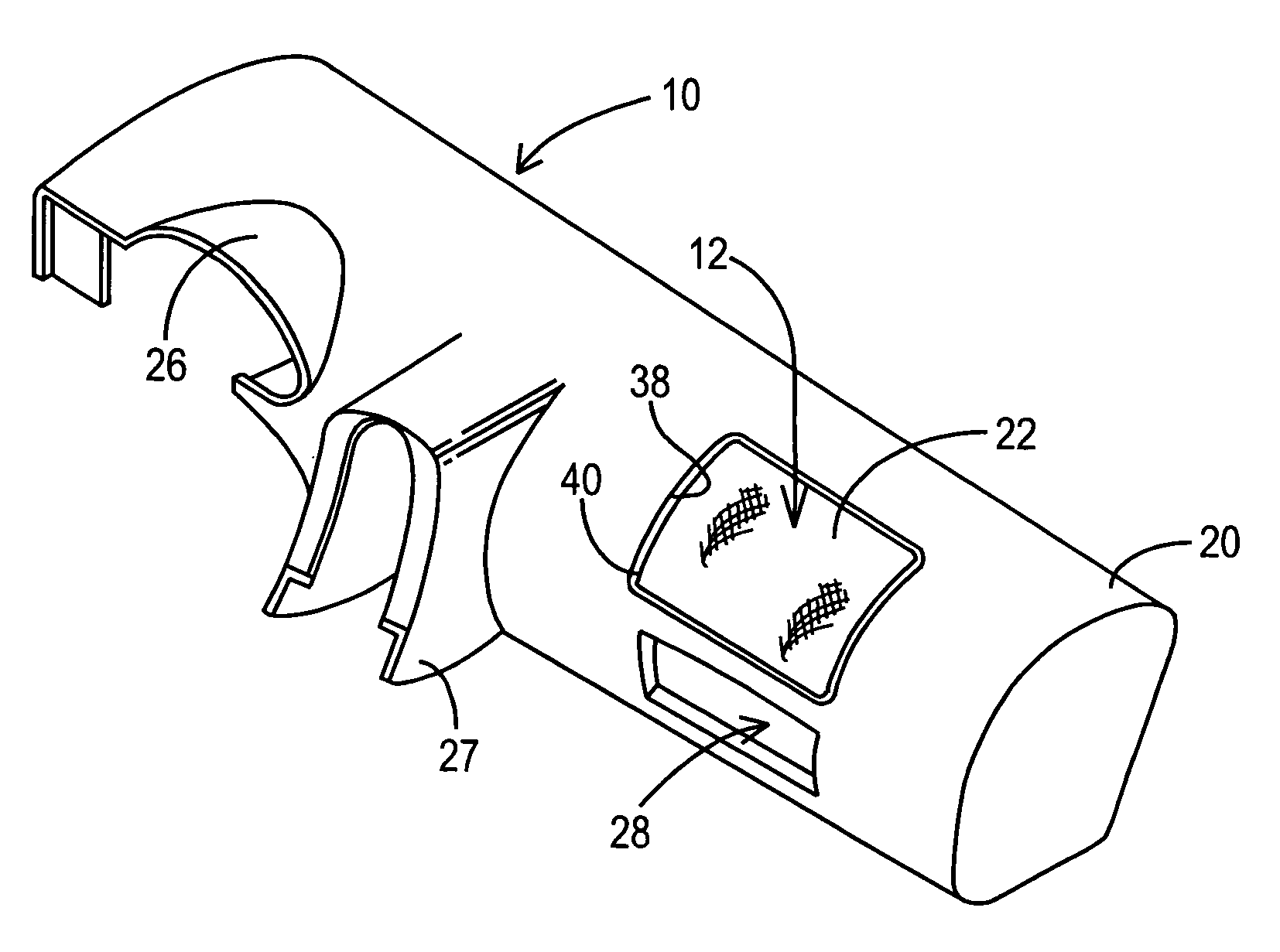
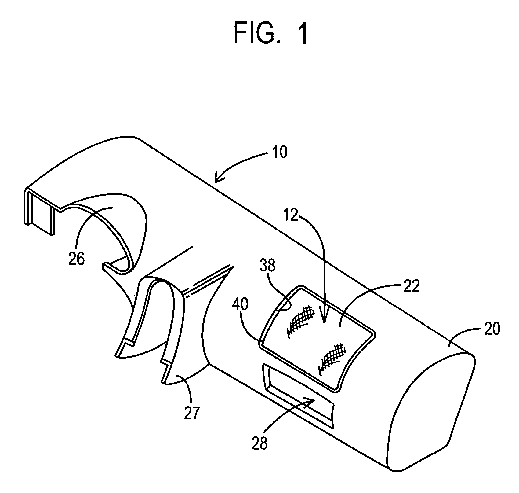
[0038] As noted above, the present invention is directed at forming a trim cover for, preferably, an instrument panel in a vehicle wherein the trim cover comprises multiple colors, different textures and / or different compositions, wherein at least one of the colors, textures and / or compositions is a fabric or cloth.

[0039] An instrument panel ...


PUM

PropertyMeasurementUnit
perimeteraaaaaaaaaa
tear strengthaaaaaaaaaa
shapesaaaaaaaaaa

Abstract

An instrument panel for a vehicle comprising a first coverstock segment having an outer surface and an inner surface and a mating edge disposed along a portion of a common perimeter of the outer surface and inner surface. A second coverstock segment is supplied having an outer surface and inner surface and a mating edge disposed along a portion of a common perimeter bounding the outer surface and the inner surface, the second coverstock segment bonded to the first coverstock segment along the respective mating edges forming a joint line. At least one of the first coverstock segment and the second coverstock segment is a cloth or fabric.

Description

CROSS REFERENCE TO RELATED APPLICATIONS [0001] This application is a continuation of International Application No. PCT / US2004 / 027338 filed Aug. 23, 2004 and published Mar. 10, 2005 as International Publication No. WO 2005 / 021309, designating the United States, and which claims benefit of U.S. Provisional Application No. 60 / 497,359 filed Aug. 21, 2003, the teachings of which are incorporated herein by reference.[0002] This invention relates to trim covers for upholstery and trim panel applications, particularly for automotive applications and, more particularly, to an instrument panel for a vehicle wherein the outer surface is formed, at least in part, of a cloth or fabric. This invention further relates to forming a tear seam in a panel which comprises a plastic interface with either a cloth or a fabric. BACKGROUND OF THE INVENTION [0003] Upholstery surfaces and adjacent panels in home and office environments as well as inside transportation vehicles are generally covered with a sof...

Claims


Application Information

Patent Timeline
Patent Type & Authority Applications(United States)
IPC IPC(8): B32B3/00B32B37/00B29C65/02B32B3/04B32B3/10B32B5/26B32B27/12B60KB60K37/00D04H1/00D04H13/00
CPCB29C65/02Y10T428/19B29C66/24B29C66/24244B29C66/30223B29K2313/00B29L2031/3008B60K37/00B29C66/1122B29C66/729B29C66/5326B29C66/472B29C65/00B29C65/08B29C65/1412B29C65/16B29C65/1635B29C65/1696B29C65/18B29C65/04B29C66/71B29C66/712B29C66/61B29K2027/06B29K2067/00B32B5/26D04H13/00D04H1/76
Inventor GRAY, JOHN D.BATCHELDER, BRUCE
Owner COLLINS & AIKMAN PROD CO
Why Eureka
Try Eureka