Device to record sensor measurement locations

Inactive Publication Date: 2006-08-10
WIBLIN CLAUDE MELVIN +1
View PDF2 Cites 0 Cited by
  • Summary
  • Abstract
  • Description
  • Claims
  • Application Information

AI Technical Summary

Problems solved by technology

Previous art devices measure distance but these devices do not determine the location using Cartesian coordinates.
However, these only measure linear distances and do not provide the location of a sensor reading using Cartesian coordinates.

Method used


Image

  • Device to record sensor measurement locations
  • Device to record sensor measurement locations
  • Device to record sensor measurement locations

Examples


Embodiment Construction

Operation

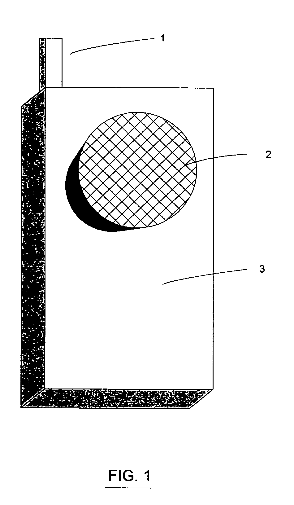
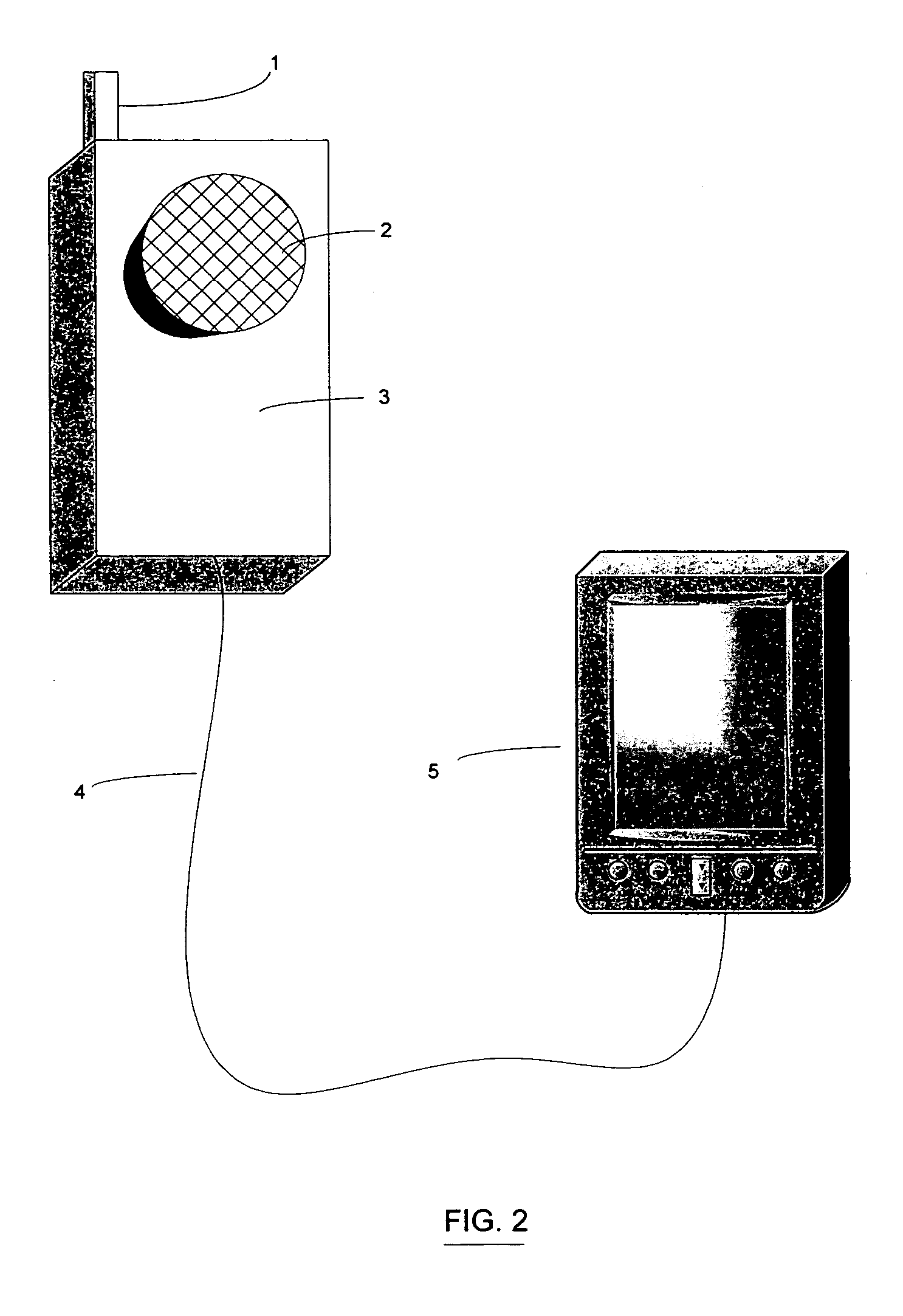
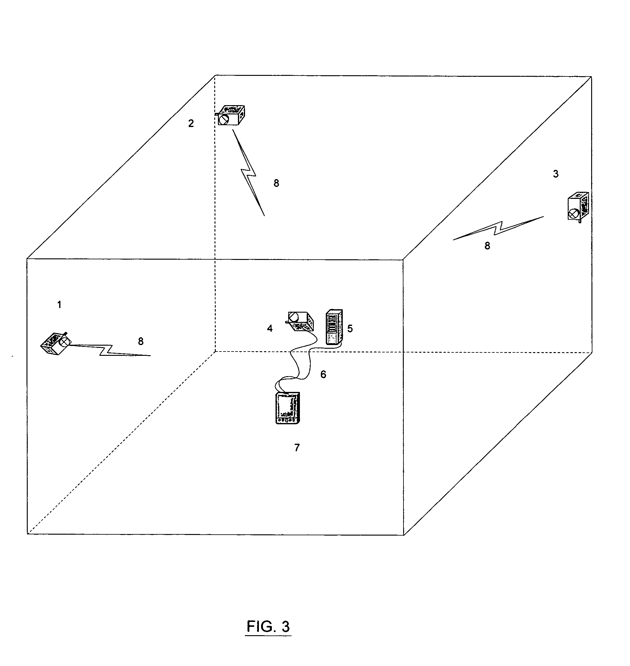
[0016] The manner of using the device to record sensor measurement locations is first: to set two or more of the transmitters in a configuration with the distances known between them; second: attach the receiver to the sensor device; third: log receipts of transmission with date and time interval to the second of each with the parallel input of sensor readings; fourth: input recorded data onto screen for user or into file for later evaluation. By knowing the locations of the transmitters and the distance to the receiver from each transmitter, triangulation is made to determine Cartesian coordinates and the velocity of the sensor. Maps can be generated in real-time on the logging device or later as desired.

[0017] The device is able to determine the location of the receiver at all times by knowing where the transmitters are and then measuring the distance from those transmitters to the receiver. For example, when surveying a floor, two transmitters are placed at one end of...


PUM


Abstract

A device to record the location, expressed as Cartesian coordinates, of sensor readings, to be attached to a sensor, such as a radiation sensor. The device comprises a plurality of transmitters, a plurality of receivers, processing means, display, and storage means. The processing means calculates the Cartesian coordinates and displays and records the coordinates of each sensor reading.

Description

CROSS-REFRENCE TO RELATED APPLICATION [0001] This application is entitled to the benefit of U.S. Provisional Patent Application Ser. No. 60 / 651,766 filed 2005 Feb. 10.FEDERALLY SPONSORED RESEARCH [0002] Not Applicable SEQUENCE LISTING OR PROGRAM [0003] Not Applicable BACKGROUND—FIELD OF INVENTION [0004] This invention relates to ultrasound distance measurement technology. BACKGROUND—DESCRIPTION OF PRIOR ART [0005] Ultrasound devices used to measure distance are well known in the prior art. Previous art devices measure distance but these devices do not determine the location using Cartesian coordinates. [0006] One device that tracks the location using ultrasound is identified in U.S. Pat. No. 6,765,491. Another device that tracks location using ultrasound is identified in U.S. Pat. No. 5,631,875. However, these only measure linear distances and do not provide the location of a sensor reading using Cartesian coordinates. They also do not show sensor readings simultaneously recorded at...

Claims


Application Information

Patent Timeline
IPC IPC(8): G01B5/28
CPCG01S5/30G01S11/16
Inventor WIBLIN, CLAUDE MELVINWIBLIN, BRIAN DAVID
Owner WIBLIN CLAUDE MELVIN
Why Eureka
Try Eureka