
Method for monitoring tire pressure variation of automobile tire and system for realizing the same

Inactive Publication Date: 2006-08-10
SHANTOU HI TECH ZONE TONKI MOTORCAR SCI & TECH
View PDF4 Cites 4 Cited by
  • Summary
  • Abstract
  • Description
  • Claims
  • Application Information

AI Technical Summary

Benefits of technology

[0005] An object of the present invention is to provide a monitoring method with high alarm accuracy, which can perform data sampling in accordance with current concrete conditions of individual tires of the vehicle so as to establish a set of rotation speed data of the individual tires, compare these data with the real-time measured or measured and calculated rotation speeds of individual tires, forecast the tire pressure variations and raise alarms in case of overpressure or underpressure.

Problems solved by technology

The main disadvantage of this direct measurement-type device is that the tire pressure variations are large at different speeds, thus resulting in such problems that the critical value for tire pressure alarm is difficult to set and facile error alarm may be raised.
Theoretically, the tire pressure variations will cause changes in the effective radius of the tires and thus cause different rotation speeds of the tires.
In fact, however, the effective radius of individual tires of the motor vehicles are generally different form each other due to not only different brands but also different wearing degrees, and thus resulting in different rotation turns of individual tires at the same speed.
Therefore, there is still problem such as low accuracy of alarm in the method or system that establishes corresponding standards only in accordance with specifications of the tires so as to suit different conditions for comparison and judgment.
In addition, such method and system cannot determine the tire pressure variations when the vehicle is turning and are also difficult to judge location of the fault tire properly.

Method used


Image

  • Method for monitoring tire pressure variation of automobile tire and system for realizing the same
  • Method for monitoring tire pressure variation of automobile tire and system for realizing the same
  • Method for monitoring tire pressure variation of automobile tire and system for realizing the same

Examples


Embodiment Construction

[0114] The detailed embodiment mode of the system and method according to the present invention is further explained as follows combined with the attached drawings:

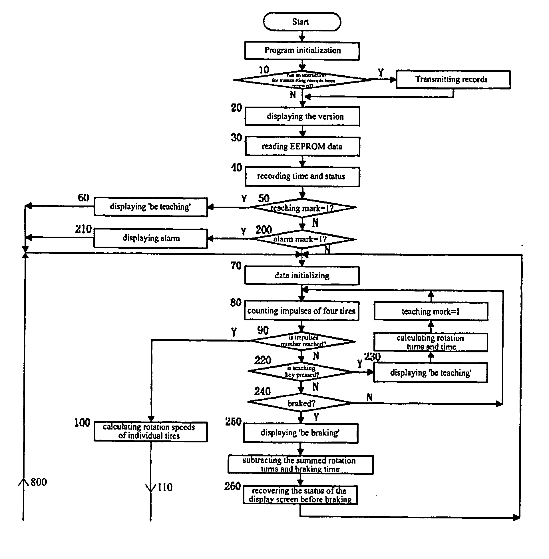
[0115] The step or procedure design of the embodiment is divided into two parts, i. e., reference rotation speed difference Vd establishment part and measured and calculated rotation speed difference Vc establishment part, and there are some common procedures between these two parts, so that they can be designed as another common part that mainly comprises measurement of rotating turns of individual tires, inspection of data effectiveness and calculation of rotation speeds of individual tires, and two parts are separated each other and enter individual substantial procedure after judging the teaching mark. A reference value establishment portion comprises a process of establishment of the reference value which is regarded as the basis for determining tires in case of underpressure and the locations thereof, a reference v...


PUM


Abstract

A method for monitoring tire pressure variation of automobile tires and a system of implementing thereof, which measures and obtains rotation speeds of individual automobile tires as reference values, and compares these reference values with the current rotation speeds of individual automobile tires to inspect tire pressure variation of automobile tires and provide basis for determining fault tire locations. Compared with the conventional art, it has advantages to determine fault locations accurately, and deal with the problem of misreporting tire locations due to the influence in determining fault locations by the difference of specifications of tires, pressure or wearing degrees. In addition, the method and system can raise an alarm when two tires arranged axially or diagonally are in case of equal underpressure, and record data relating to the alarm signal and rotation speeds as the basis for distinguishing liabilities in case of accidents.

Description

The present invention claims the benefit of the U.S. patent application US10 / 940,482, which is hereby incorporated by reference for all purposes as if fully set forth herein.FIELD OF THE PRESENT INVENTION [0001] The present invention relates to a method and a system for detecting indirectly the tire pressure variations of automobile tire, more particularly, to a detection method and system for judging the tire pressure variation by detecting rotation turns of the wheels, calculating rotation speeds of the wheels, comparing and analyzing these rotation speeds. DESCRIPTION OF THE RELATED ART [0002] In prior art, pressure sensors are generally installed on the tires for measuring tire pressure of running vehicles and sending overpressure and underpressure alarms according to the measured tire pressure. The main disadvantage of this direct measurement-type device is that the tire pressure variations are large at different speeds, thus resulting in such problems that the critical value f...

Claims


Application Information

Patent Timeline
IPC IPC(8): G01L13/00
CPCB60C23/061G01L13/00
Inventor CHEN, HAOSHENGZHU, YOUCONG
Owner SHANTOU HI TECH ZONE TONKI MOTORCAR SCI & TECH
Learn More