Storage system, backup system, and backup method

Active Publication Date: 2006-08-10
GOOGLE LLC
View PDF15 Cites 4 Cited by
  • Summary
  • Abstract
  • Description
  • Claims
  • Application Information

AI Technical Summary

Benefits of technology

[0011] Accordingly, it is an object of the present invention to provide a technique which makes it possible to respond to a server that pair volumes are in a split state. The technique also assures consistency of data even in a case where the data is transferred to a backup device using a backup command, and it enables backup without urging the server's processing to wait.

Problems solved by technology

Thus, there is a tendency for the load imposed on backup processing of a server to be increased.
However, as the amount of data increases, the server resources (e.g., host bus adapter) used for the backup are occupied for a longer time.
Thus, if another application program tries to use this host bus adapter to send and receive other data during this interval, the processing has to wait for a long time or the performance deteriorates greatly.
Therefore, the consistency between the data transferred from the target volume to the backup device and the data in the source volume is not assured.
Furthermore, if a backup is performed after waiting until data to be updated is completely reflected in the target volume from the source volume, the server waits without being capable of giving an instruction for start of backup processing until the data to be updated is completely reflected in the target volume.

Method used


Image

  • Storage system, backup system, and backup method
  • Storage system, backup system, and backup method
  • Storage system, backup system, and backup method

Examples


first embodiment

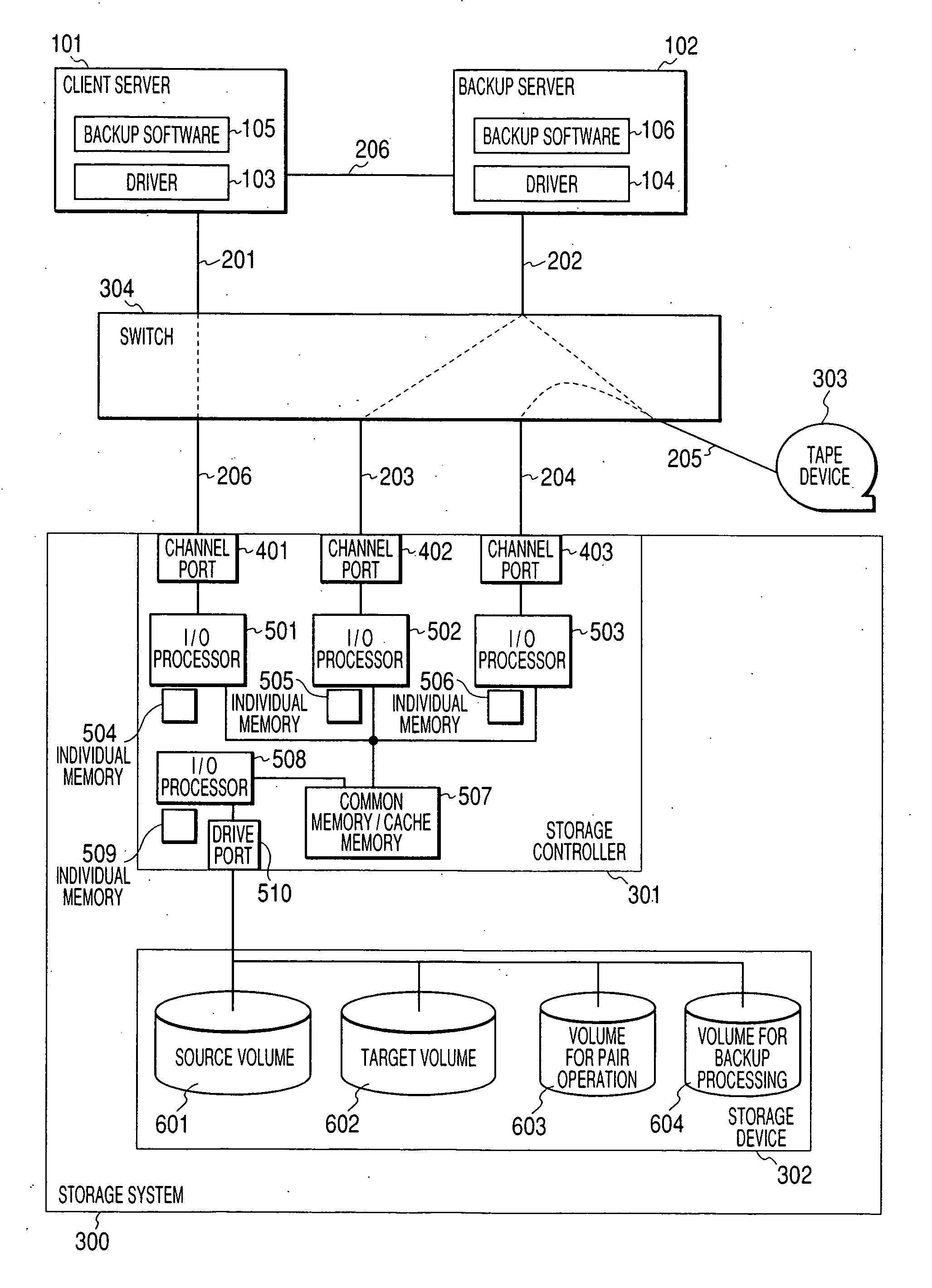
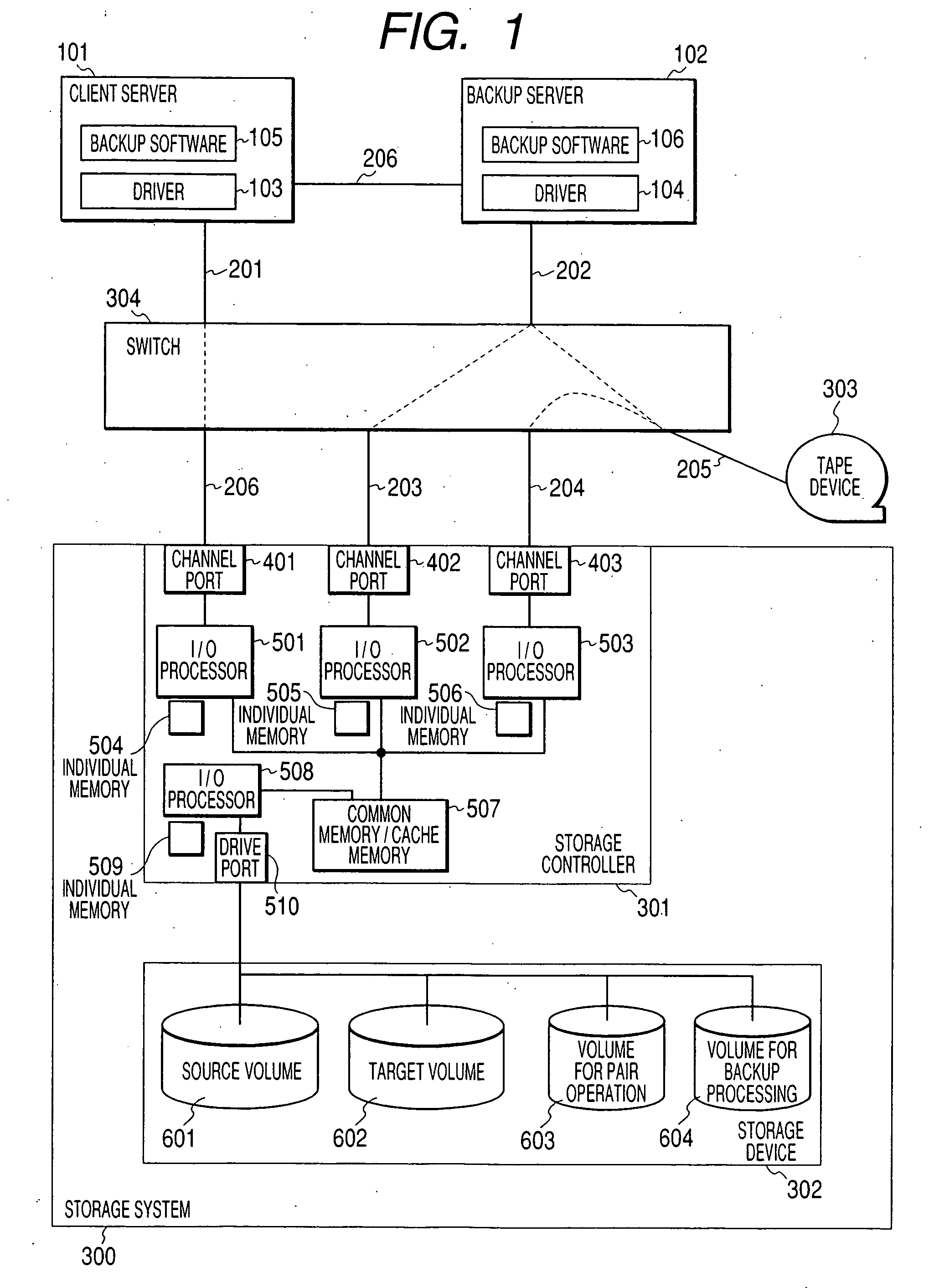
[0026]FIG. 1 is a diagram showing the configuration of a storage system 300 in a first embodiment of the present invention. In the storage system 300, a storage controller 301 is connected with a client server 101 via a switch 304 by paths 201 and 206, and it controls I / O processing required from the client server 101. Similarly, the storage controller 301 is connected with a backup server 102 via the switch 304 by paths 202 and 203, and it controls I / O processing required from the backup server 102. Furthermore, the storage controller 301 is connected by paths 204 and 205 via the switch 304 with a tape device 303, that constitutes a backup device, and it controls I / O processing to and from the tape device 303. The client server 101, backup server 102, storage controller 301 and backup device 303 are connected via the switch 304. The switch 304 controls the route of the paths. For example, when the client server 101 issues a command to a channel port 401, the command sent from the c...

second embodiment

[0046]FIG. 5 is a conceptual block diagram of backup processing in accordance with a second embodiment. After pair splitting, if the backup server 102 issues an instruction command for backup, the storage controller 301 checks to see if differential data remains in the range to be backed up. Where differential data remains, the I / O processor 503 makes the backup command wait until all the differential data has been copied into the target volume 602. As a result, it takes a long time until the backup processing is completed, but the processing in the storage controller 301 is made simpler. In addition, the backup processing can be made to proceed without the client server 101 and backup server 102 monitoring the state of the target volume 602.

[0047]FIG. 6 is a flowchart illustrating a summary of the processing. The processing is almost identical with the first embodiment. The difference from the first embodiment is that the I / O processor 503 monitors the state of reflection of the d...

third embodiment

[0049]FIG. 8 is a conceptual block diagram illustrating the manner in which backup processing is performed using the backup data storage area 515 in a case where differential data exists from the source volume 601 to the target volume 602 after the pair volumes have been split in backup processing.

[0050] After pair splitting, if an instruction command for backup is issued from the backup server 102, the storage controller 301 checks to see whether differential data remains in the range to be backed up. Where differential data remains, the storage controller 301 reads the differential data concerning the portion to be backed up from the source volume 601 and once stores the data into the backup data storage area 515. Furthermore, if the data about the range to be backed up has been reflected in the target volume 602, the data is read into the backup data storage area 515 and merged with the data from the source volume 601. Then, the merged data is transferred to the tape device 303....


PUM


Abstract

A storage controller can perform backup processing without proceeding via a server and without the need for the server to grasp the state of pair volumes. When an instruction for backup is given from the server while data is being copied from a source volume to a target volume, the storage controller transfers the data to a backup device using differential information between the pair volumes after waiting until data about a range to be backed up and instructed by the server is copied into the target volume.

Description

CROSS-REFERENCE TO RELATED APPLICATION [0001] The present application is a continuation of application Ser. No. 10 / 784,999, filed Feb. 25, 2004 and relates to and claims priority from Japanese Patent Application No. 2003-183742, filed on Jun. 27, 2003, the entire disclosure of which is incorporated herein by reference.BACKGROUND OF THE INVENTION [0002] The present invention relates generally to the backup of information stored in a storage system, and, more particularly, to server-free backup of information on a storage area network (SAN). [0003] As computer systems have treated an increasing amount of information in recent years, there is an increasing need for backing up such information. Thus, there is a tendency for the load imposed on backup processing of a server to be increased. Where a server backs up a large amount of data, the data is read from a storage system with which a source storage device to be backed up is connected, and then the data is written into a target backu...

Claims


Application Information

Patent Timeline
IPC IPC(8): G06F15/16G06F12/00G06F3/06
CPCG06F11/1451G06F11/1464G06F11/2071G06F11/2082
Inventor IDO, TAKESHIURABE, KIICHIRO
Owner GOOGLE LLC
Why Eureka
Try Eureka