Apparatus and method for forming retaining wall blocks with variable depth flanges

a technology of variable depth flanges and retaining wall blocks, which is applied in the field of masonry blocks, can solve problems such as undesirable uniform setbacks

Active Publication Date: 2006-08-17
NESS INVENTIONS
View PDF13 Cites 21 Cited by
  • Summary
  • Abstract
  • Description
  • Claims
  • Application Information

AI Technical Summary

Benefits of technology

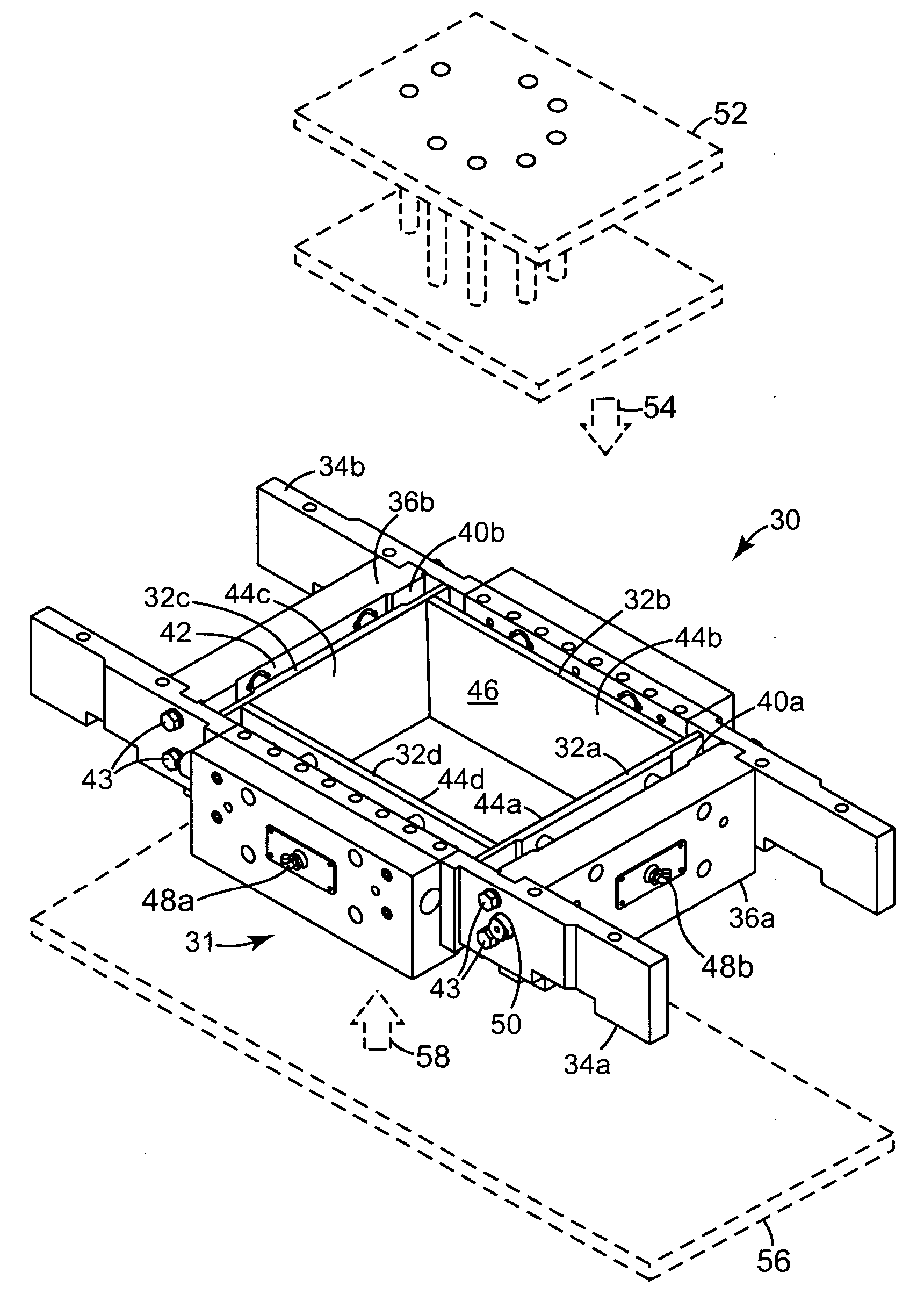
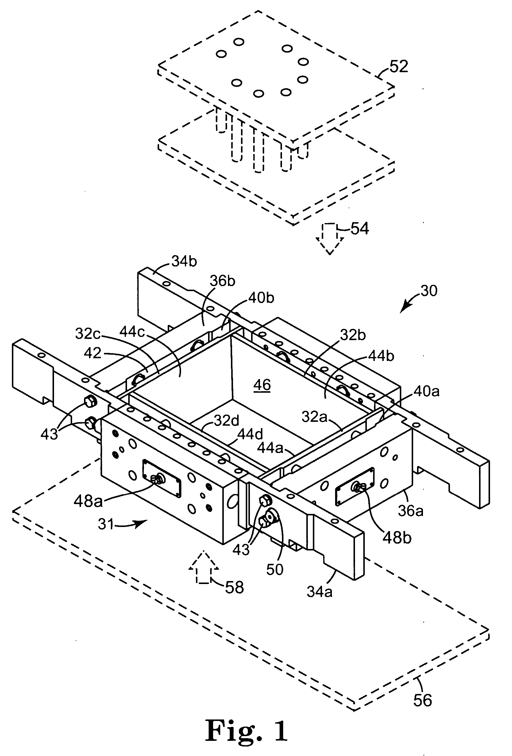
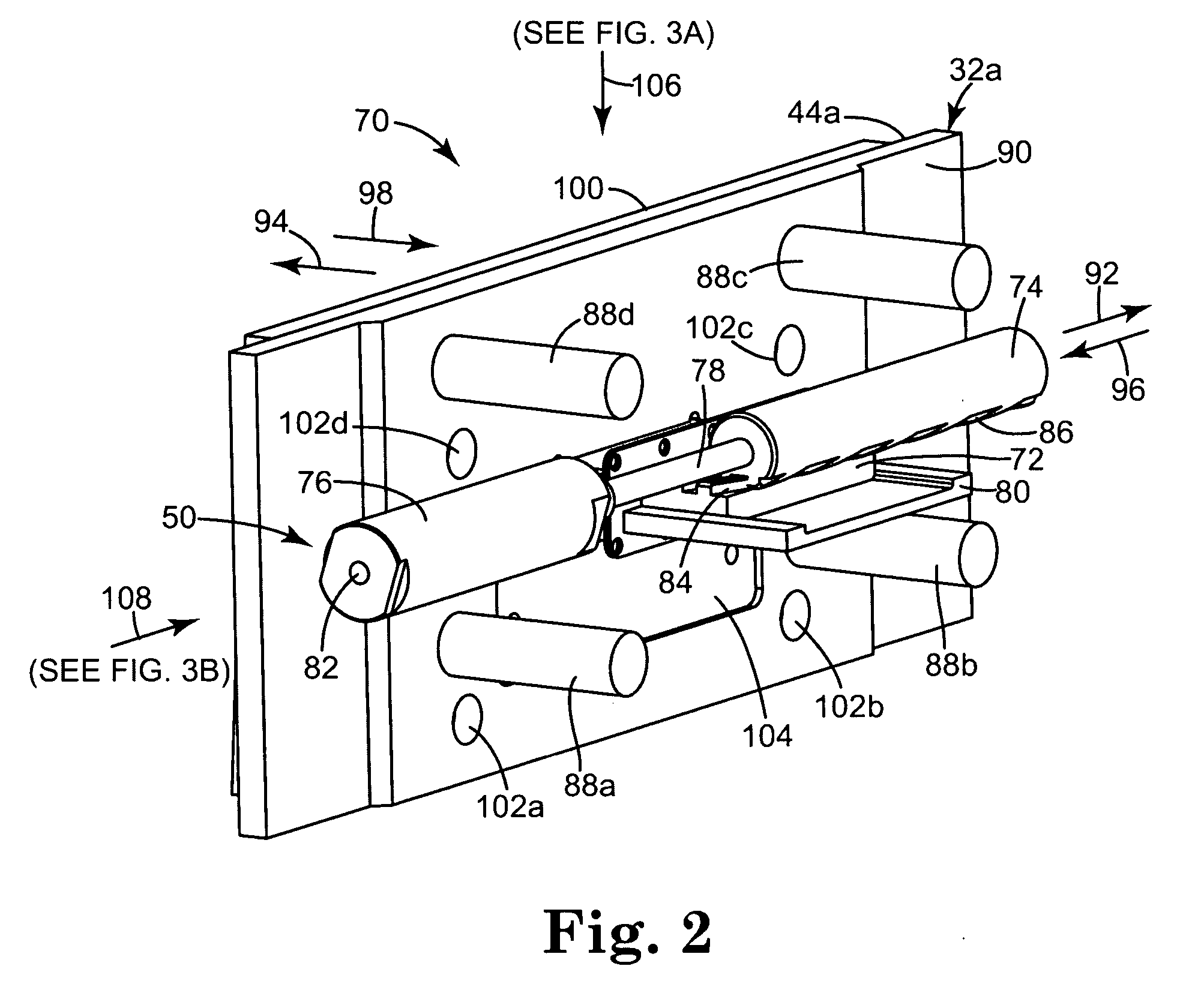
[0006] One embodiment of the present invention provides a mold assembly including a plurality of mold components configured to form a mold cavity having a desired shape, wherein at least one of the mold components has a notch configured to form a set-back flange in a masonry block formed in the mold cavity, the notch having a depth. The mold assembly further includes a moveable flange plate and a drive assembly configured to extend the moveable flange plate into and retract the moveable flange plate from the notch within a desired range of distances so as to adjust the depth of the notch.

Problems solved by technology

Such a uniform set-back can be undesirable, particularly when trying to create a landscape structure having a natural appearance, such as that of natural rock or stone.

Method used


Image

  • Apparatus and method for forming retaining wall blocks with variable depth flanges
  • Apparatus and method for forming retaining wall blocks with variable depth flanges
  • Apparatus and method for forming retaining wall blocks with variable depth flanges

Examples


Embodiment Construction

[0053] In the following Detailed Description, reference is made to the accompanying drawings which form a part hereof, and in which is shown by way of illustration specific embodiments in which the invention may be practiced. In this regard, directional terminology, such as “top,”“bottom,”“front,”“back,”“leading,”“trailing,” etc., is used with reference to the orientation of the Figure(s) being described. Because components of embodiments of the present invention can be positioned in a number of different orientations, the directional terminology is used for purposes of illustration and is in no way limiting. It is to be understood that other embodiments may be utilized and structural or logical changes may be made without departing from the scope of the present invention. The following detailed description, therefore, is not to be taken in a limiting sense, and the scope of the present invention is defined by the appended claims.

[0054] As described herein and illustrated by FIGS. ...


PUM

PropertyMeasurementUnit
angleaaaaaaaaaa
angleaaaaaaaaaa
operational angleaaaaaaaaaa

Abstract

A mold assembly including a plurality of mold components configured to form a mold cavity having a desired shape, at least one of the mold components having a notch configured to form a set-back flange in a masonry block formed in the mold cavity, the notch having a depth. The mold assembly further includes a moveable flange plate and a drive assembly configured to extend the moveable flange plate into and retract the moveable flange plate from the notch within a desired range of distances so as to adjust the depth of the notch.

Description

CROSS-REFERENCE TO RELATED APPLICATION [0001] The subject matter of this application is related to the subject matter of U.S. Provisional Patent Application No. 60 / 644,108, filed Jan. 13, 2005, priority to which is claimed under 35 U.S.C. § 119(e) and which is incorporated herein by reference.THE FIELD OF THE INVENTION [0002] The present invention relates generally to masonry blocks, and more particularly to a mold assembly and method for making retaining wall blocks with variable depth flanges for providing varying set-backs. BACKGROUND OF THE INVENTION [0003] Concrete retaining wall blocks are used to build any number of landscape structures, such as, for example, raised planting beds and soil retention walls. These structures are generally formed by stacking the retaining wall blocks on top of one another in successive courses. Typically, retaining wall blocks include some type of set-back flange extending from a lower face of the block that is designed abut against a rear face o...

Claims


Application Information

Patent Timeline
Patent Type & Authority Applications(United States)
IPC IPC(8): B28B7/02B28B3/00E04C2/04
CPCB28B1/008B28B1/32B28B1/52B28B7/0079B28B23/0087E04C1/395
Inventor NESS, JEFFREY A.
Owner NESS INVENTIONS
Why Eureka
Try Eureka