
Roof edge fall protection apparatus

a technology of fall protection and roof edge, which is applied in the direction of fencing, construction, buildings, etc., can solve the problems of high risk of flat roof work, destruction of materials used when disassembled after a job is completed, and little or no labour saving in the construction of such temporary barriers, so as to achieve easy assembly and disassembly on site

Inactive Publication Date: 2006-08-17
THALER KEN
View PDF3 Cites 18 Cited by
  • Summary
  • Abstract
  • Description
  • Claims
  • Application Information

AI Technical Summary

Benefits of technology

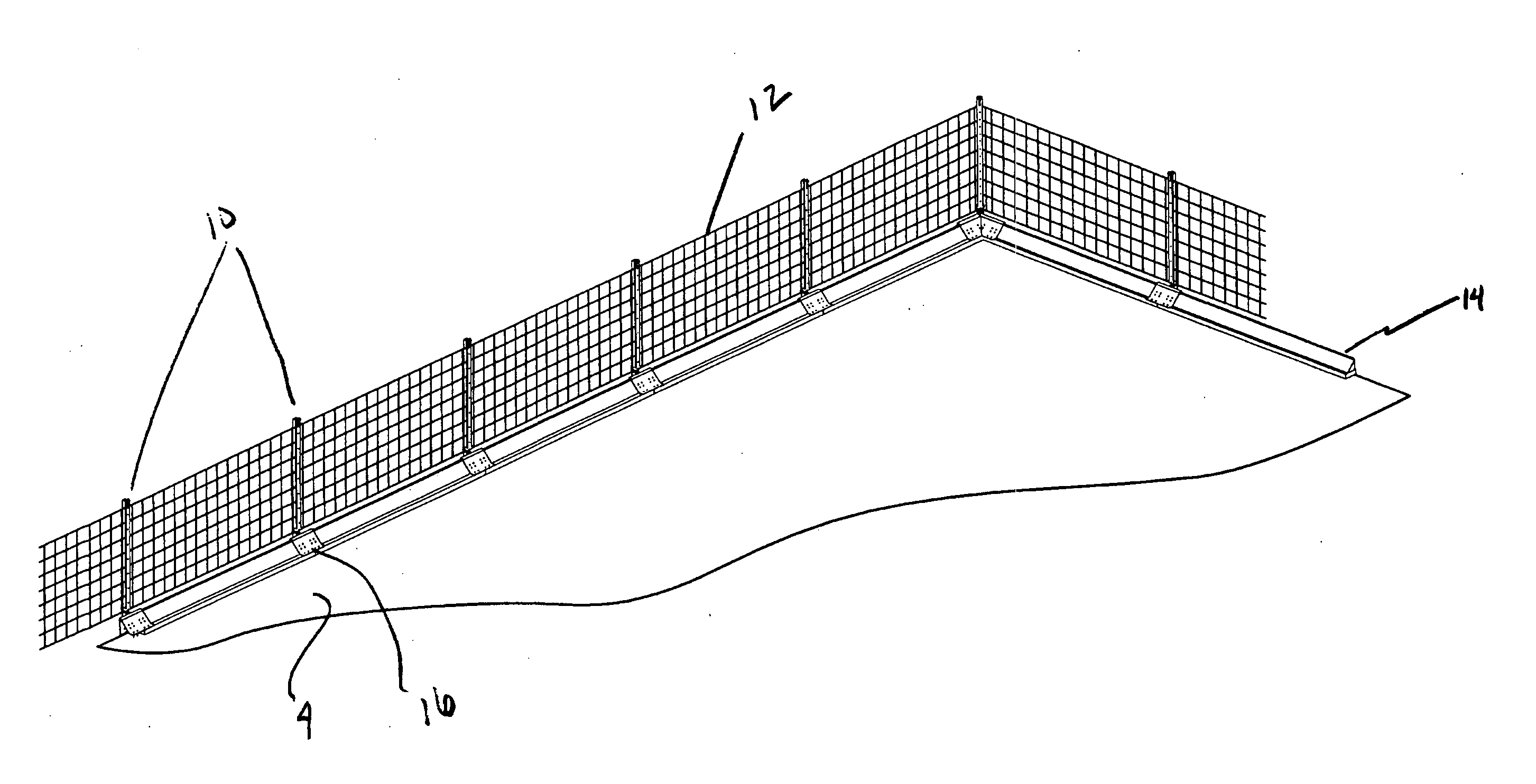
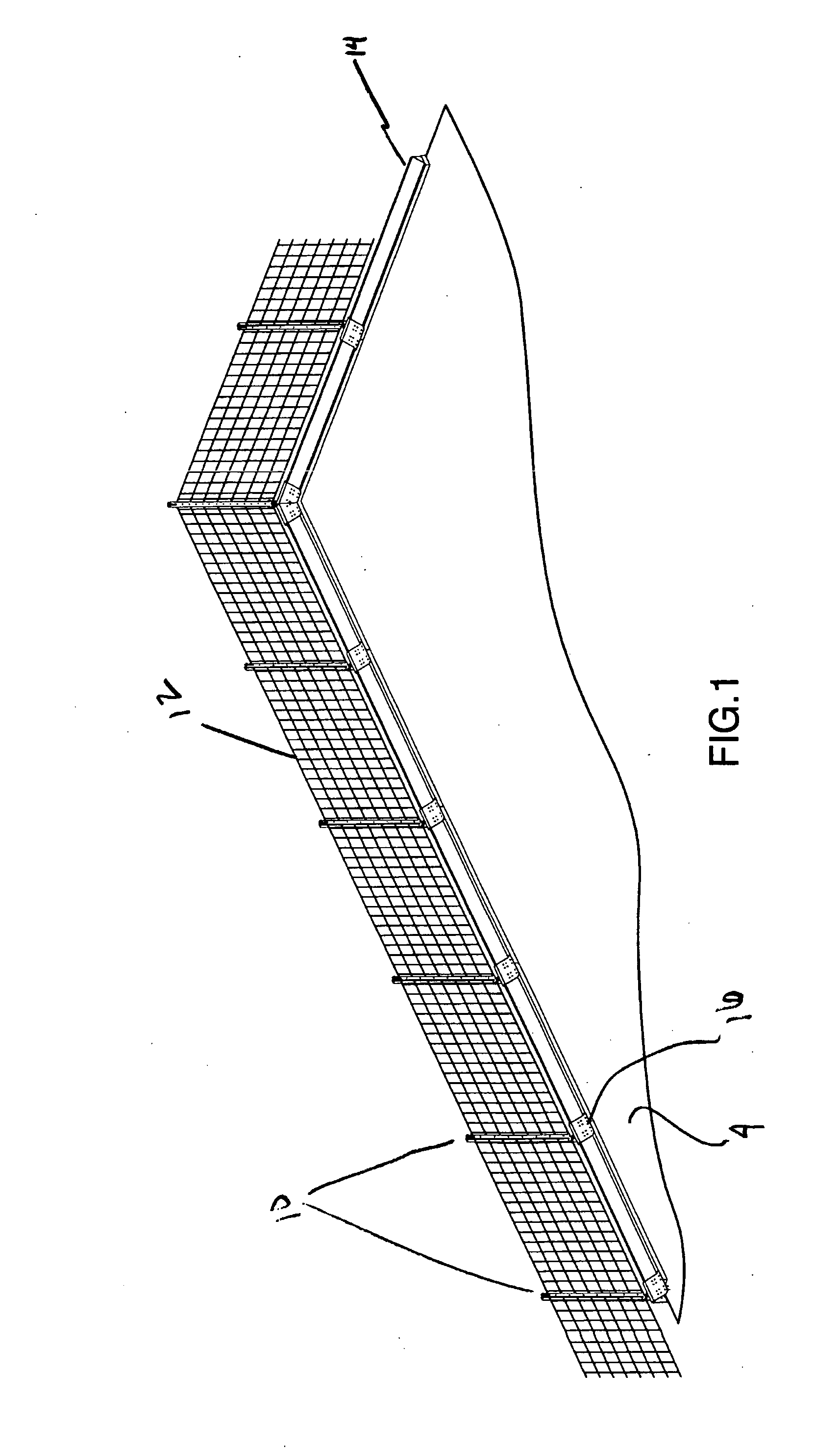
[0010] The present invention relates to an improved roof edge fall protection apparatus. Most industrial and commercial buildings having flat roofs will have a parapet wall around the perimeter edge of the roof. The height and configuration of the parapet wall will vary from structure to structure. Roof edge fall protection devices are typically installed at or near such parapet walls. The apparatus of the present invention comprises several components that can be easily assembled and disassembled on site and which are adaptable to various building geometries.

Problems solved by technology

Working on a flat roof is high risk.
Such temporary barriers may meet regulatory requirements if properly constructed, but require a fair amount of time to construct and often result in the destruction of materials used when disassembled after a job is completed.
This results in little or no labour saving in the construction of such temporary barrier even if materials are re-used.
While such cantilevered systems may be permanent or temporary they also interfere with the roofing work to be done.

Method used


Image

  • Roof edge fall protection apparatus
  • Roof edge fall protection apparatus
  • Roof edge fall protection apparatus

Examples


Embodiment Construction

[0025] The description, which follows, and the embodiments described therein, is provided by way of illustration of an example, or examples of particular embodiments of principles and aspects of the present invention. These examples are provided for the purposes of explanation, and not of limitation, of those principles and of the invention. In the description that follows, like parts are marked throughout the specification and the drawings with the same respective reference numerals.

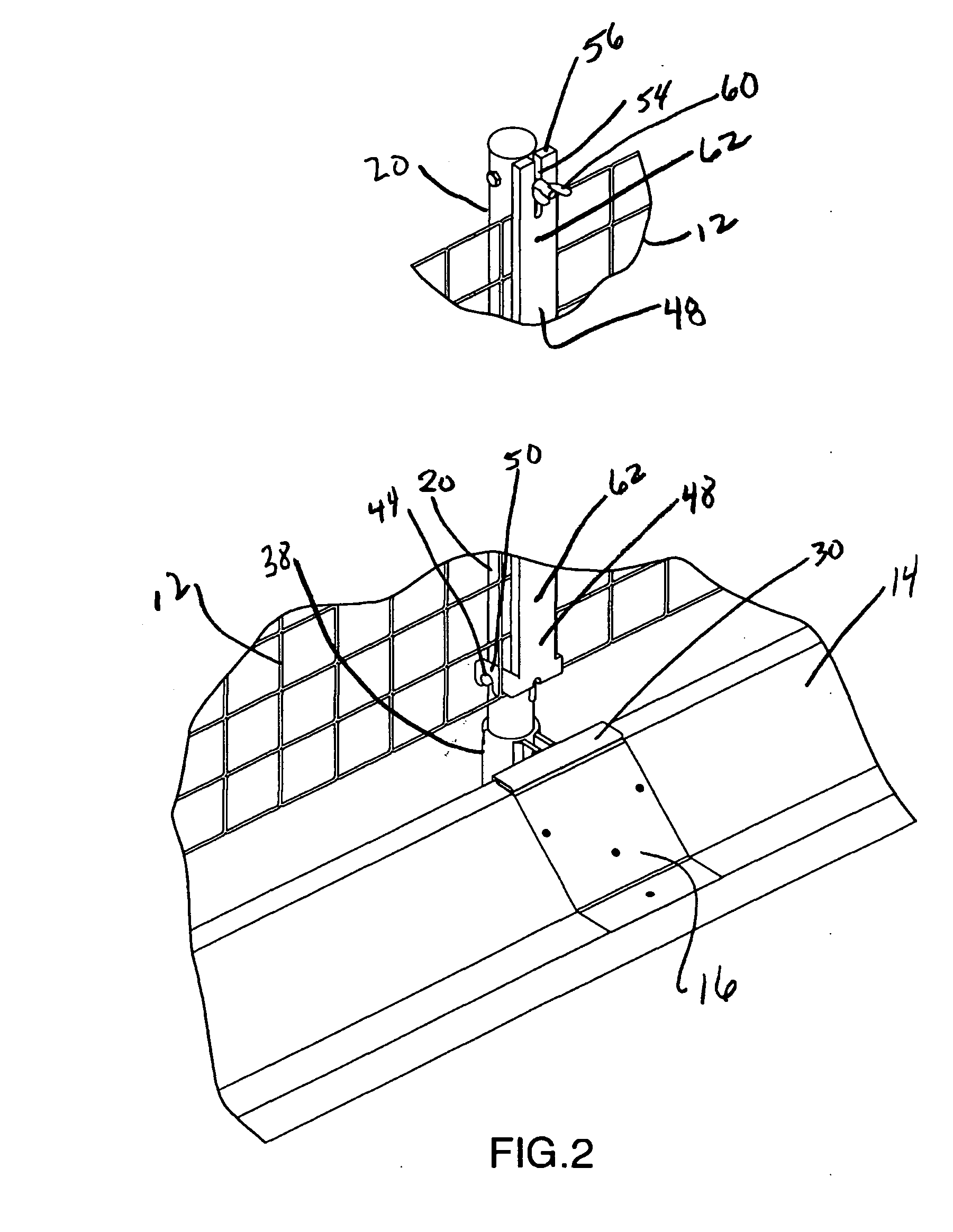
[0026] Referring to the drawings there is illustrated a roof edge fall protection apparatus generally designated 2 which includes a plurality of spaced apart upright support members 10. The support members are of a height to form a sufficient barrier to prevent a human from falling off the roof. The support members 10 are removably affixed at the edge of the roof 4 of the building 6 typically on a parapet 14. Such parapet may have sloped walls. An elongate barrier member, shown as a safety mesh fence 1...


PUM


Abstract

The present invention relates to roof edge fall protection devices typically installed at or near such parapet walls. The apparatus of the present invention comprises several components that can be easily assembled and disassembled on site and which are adaptable to various building geometries. The apparatus comprises at least two support members, each comprised of a roof mounting portion including a first base plate member that is securely mountable on the roof of the building structure and a second base plate member that is securely and removably mountable on the wall of the building structure. A side edge portion of the first base plate member is positioned substantially adjacent to the wall. A top edge portion of the second base plate member securely and removably engages the side edge portion of the roof base plate member. A barrier mounting portion including a substantially upright post member securely engages the roof mounting portion, and a barrier holding member securely engages the post member. An elongate safety barrier member securely and removably engages each barrier holding member, with the safety barrier member securely extending between at least two support members.

Description

FIELD OF THE INVENTION [0001] The present invention relates generally to a roof edge fall protection apparatus for flat roofs and parapets that serves to protect workers in the roofing industry and the like. The apparatus is adaptable to be permanently or temporarily affixed to the edge of the roof. BACKGROUND OF THE INVENTION [0002] Working on a flat roof is high risk. People may fall from the edge of a complete roof or from the edge where work such as roofing installation or re-roofing is being carried out. Safety in the work environment has become increasingly important and preventative measures are required during work on flat roofs where there is a risk of falling. Apart from horizontal lifeline fall protection systems, which may be in place, protective measures are typically required at the roof edge. Such edge protection needs to be strong enough to withstand a person falling against it. [0003] Many regulatory bodies have implemented a multitude of various requirements and st...

Claims


Application Information

Patent Timeline
IPC IPC(8): E04G3/26E04H17/14
CPCE04G21/3223E04H17/161E04G2005/148
Inventor THALER, KEN
Owner THALER KEN
Learn More