
Ambient light filter structure

a light filter and ambient technology, applied in the direction of optical radiation measurement, instruments, spectrometry/spectrophotometry/monochromators, etc., can solve the problems of unnecessary power consumption of the sensing process of non-visible illuminants, electrical circuit misunderstanding, etc., and achieve excellent ir blocking

Active Publication Date: 2006-08-17
CAPELLA MICROSYSTEMS (TAIWAN) INC
View PDF6 Cites 75 Cited by
  • Summary
  • Abstract
  • Description
  • Claims
  • Application Information

AI Technical Summary

Benefits of technology

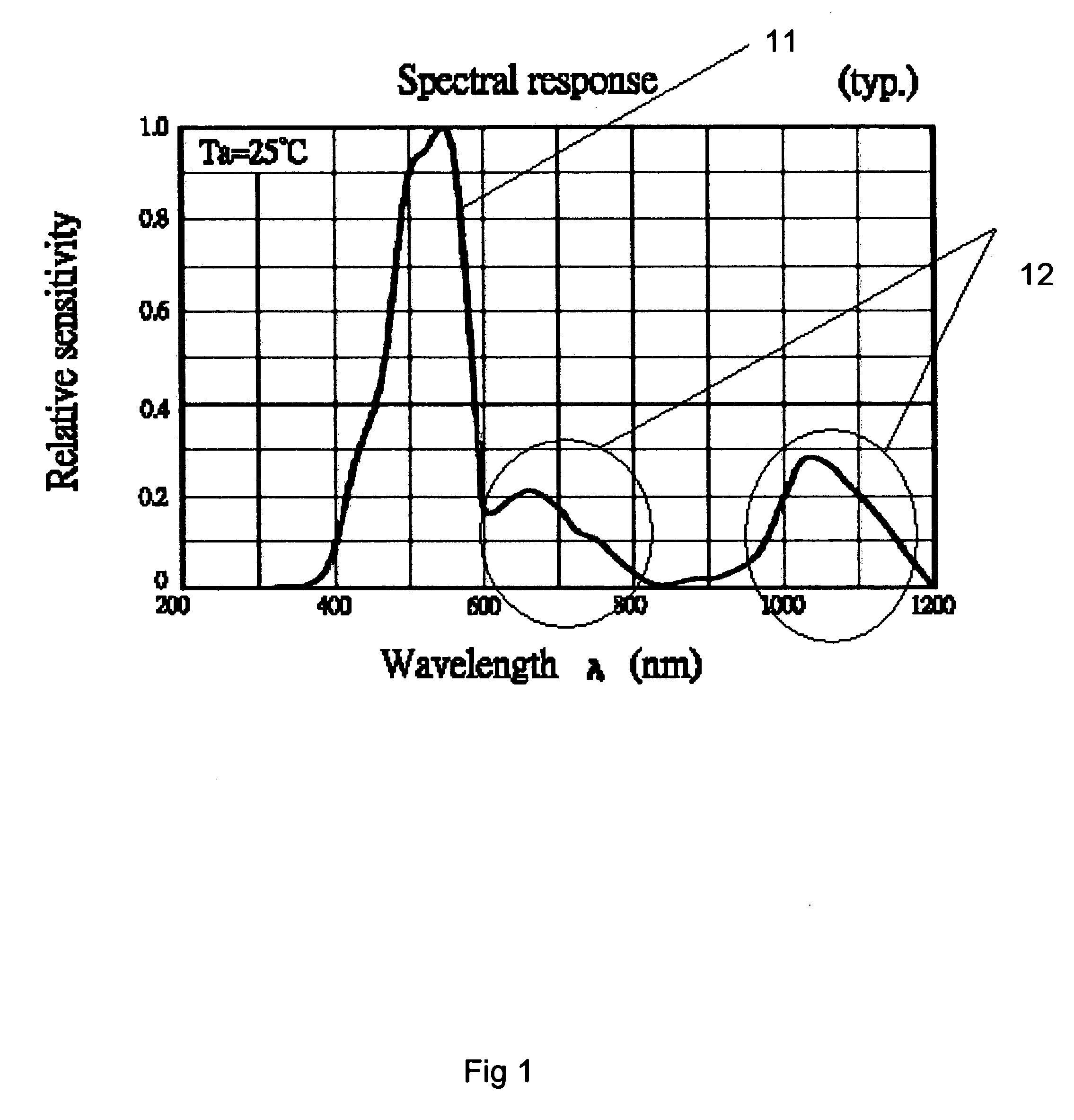
"The present invention provides an ambient light filter structure that can effectively block non-visible illuminant spectra and has a typical transmittance of less than 2% for the entire IR range of 700 nm to 1100 nm. The spectral response of the ambient light filter structure matches with human eye spectra band response by Fabry-Perot optical cavity. Additionally, the invention provides an ambient color filter structure for color sensing in a color sensor system, which can effectively block specific color wavelength spectra and has a typical transmittance of less than 2% for the entire IR range of 700 nm to 1100 nm."

Problems solved by technology

Furthermore, the ambient light sensors may cause electrical circuit misunderstandings due to the wide response for passing wavelength spectrum.
In another word, the ambient light sensor also sensitizes non-visible illuminants that human eye is unable to response and the process for sensitizing non-visible illuminants is unnecessary power consumption.

Method used


Image

  • Ambient light filter structure
  • Ambient light filter structure
  • Ambient light filter structure

Examples


Embodiment Construction

[0013] Preferred embodiments of the present invention will be explained below with reference to the drawing.

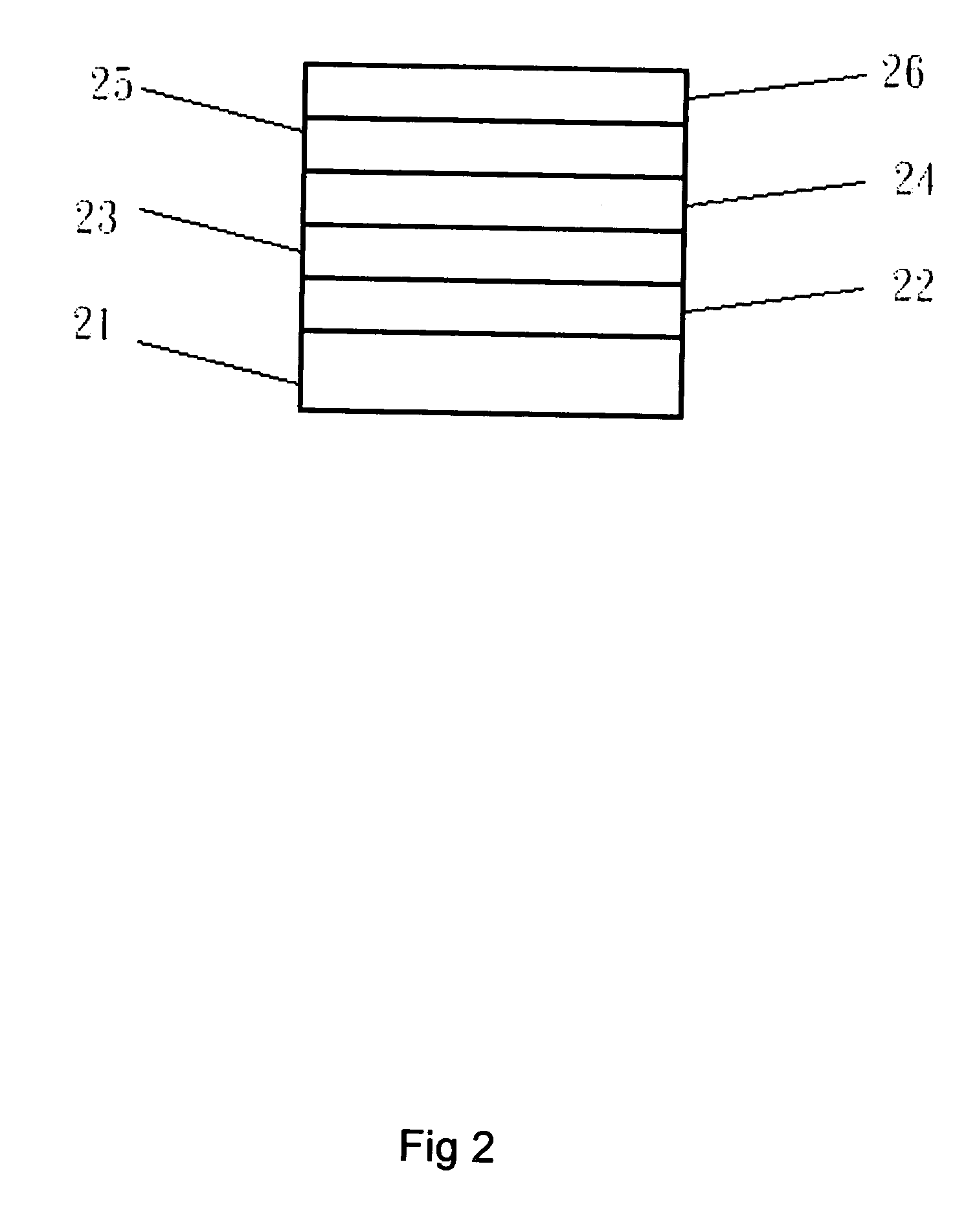
[0014]FIG. 2 shows an example of an ambient light filter structure according to an embodiment of the present invention. The ambient light filter structure comprises a silicon substrate 21, a first silicon nitride (Si3N4: 3200A+−200) component layer 22, a first silver (Ag: 285A+−35) component layer 23, a second silicon nitride (Si3N4: 920A+−50) component layer 24, a second silver (Ag: 285A+−35) component layer 25, and a third silicon nitride (Si3N4: 3500A+−200) component layer 26. The silicon substrate 21 is a foundation layer (The foundation layer may laminate over a N+ junction of a photo diode sensor region), the first silicon nitride (Si3N4: 3200A+−200) component layer 22 laminated over the silicon substrate 21, the first silver (Ag: 285A+−35) component layer 23 laminated over the first silicon nitride component layer 22, the second silicon nitride (Si3N4: 920A+−50) compon...


PUM


Abstract

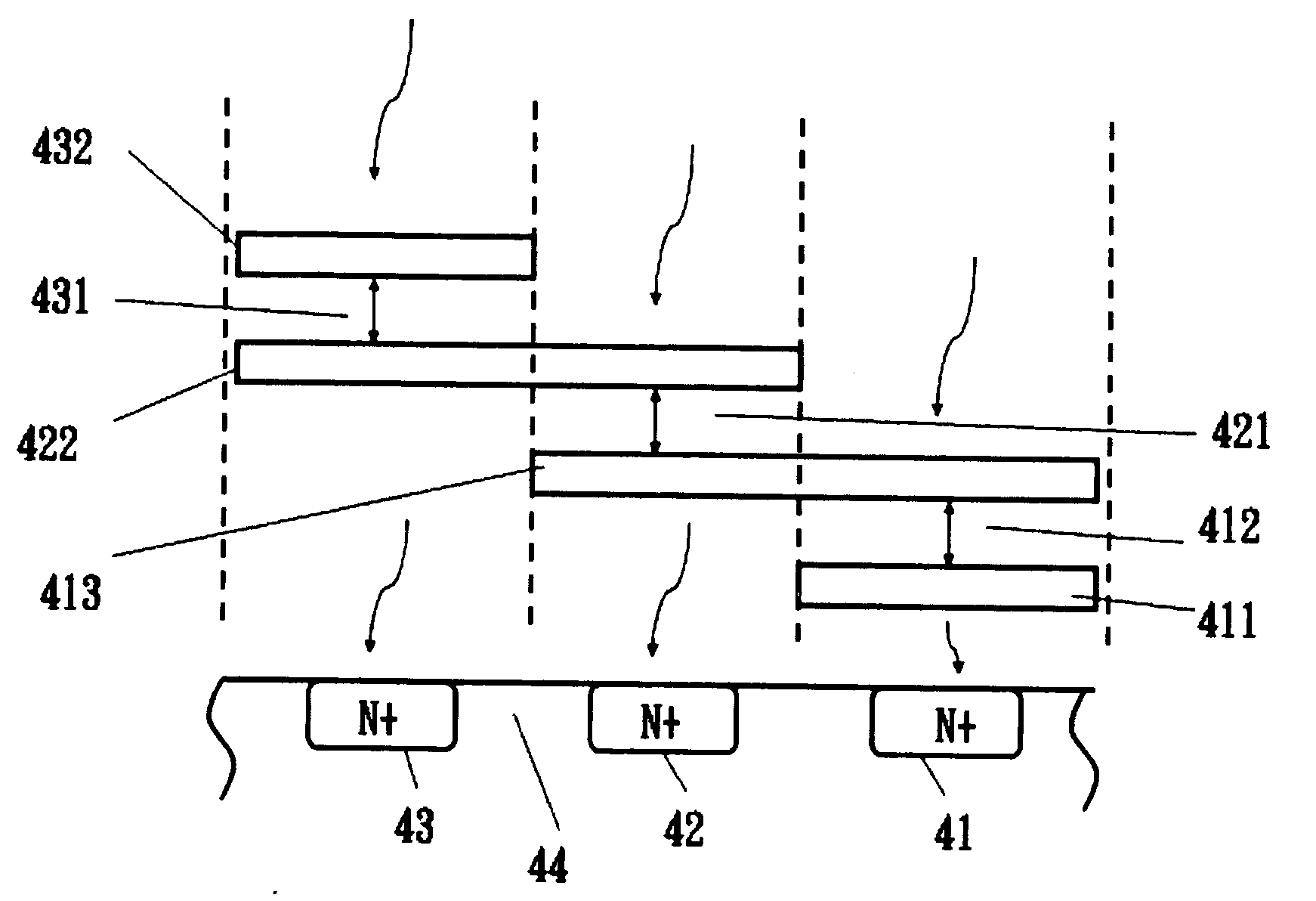
An ambient light filter structure and its response are disclosed. The ambient light filter structure comprises a silicon substrate, a first silicon nitride (Si3N4: 3200A+−200) component layer, a first silver (Ag: 285A+−35) component layer, a second silicon nitride (Si3N4: 920A+−50) component layer, a second silver (Ag: 285A+−35) component layer, and a third silicon nitride (Si3N4: 3500A+−200) component layer. Another ambient color filter structure is disclosed and further comprises a first sliver component layer, a first silicon nitride (Si3N4) component layer, second sliver (Ag) component layer, a second silicon nitride (Si3N4) component layer, a third sliver (Ag) component layer, a third silicon nitride (Si3N4) component layer, and a fourth sliver (Ag) component layer. The ambient light filter structure is set in laminating over the ambient light sensor in order to accomplish IR blocking with the photometric wavelength from 700 nm to 1100 nm. The ambient color filter structure is applied in a color sensor system for providing the specific color spectra that human eyes could recognize.

Description

CROSS REFERENCE TO RELATED APPLICATIONS [0001] This application is based upon U.S. Provisional Application No. 60 / 653,507 filed 17 Feb. 2005; U.S. Provisional Application No. 60,653,505 filed 17 Feb. 2005; and U.S. Provisional Application No. 60 / 666,589 filed 31 Mar. 2005. FIELD OF THE INVENTION [0002] The present invention generally relates to an ambient light filter structure and its response, and more particularly relates to an ambient light filter structure accomplish IR blocking range from 700 nm to 1100 nm. BACKGROUND OF THE INVENTION [0003] Ambient light sensors are now in widespread use, including cameras, camcorders, scanners, electrical microscopes, and so forth. The function of the ambient light sensors is to transfer illuminant into an electronic signal. Moreover, the ambient light sensors are used to detective ambient light whether sufficient in order to decide to provide a backlight or not. The sensitivity and the range of the ambient light sensors are higher than huma...

Claims


Application Information

Patent Timeline
Patent Type & Authority Applications(United States)
IPC IPC(8): H01L31/0232
CPCG02B5/282G02B5/288H01L27/14621H01L31/02162
Inventor TSANG, KOON WING
Owner CAPELLA MICROSYSTEMS (TAIWAN) INC
Learn More