Force distributing system for delivering a self-expanding stent

a self-expanding, stent technology, applied in the field of biomedical systems for treating vascular conditions, can solve problems such as reducing the effective length of the sten

Inactive Publication Date: 2006-08-17
MEDTRONIC VASCULAR INC
View PDF4 Cites 75 Cited by
  • Summary
  • Abstract
  • Description
  • Claims
  • Application Information

AI Technical Summary

Problems solved by technology

This can result in crumpling or buckling of the stent (sometimes referred to as a “train wreck”), reducing the effective length of the stent or even causing it to fail.

Method used


Image

  • Force distributing system for delivering a self-expanding stent
  • Force distributing system for delivering a self-expanding stent
  • Force distributing system for delivering a self-expanding stent

Examples


Embodiment Construction

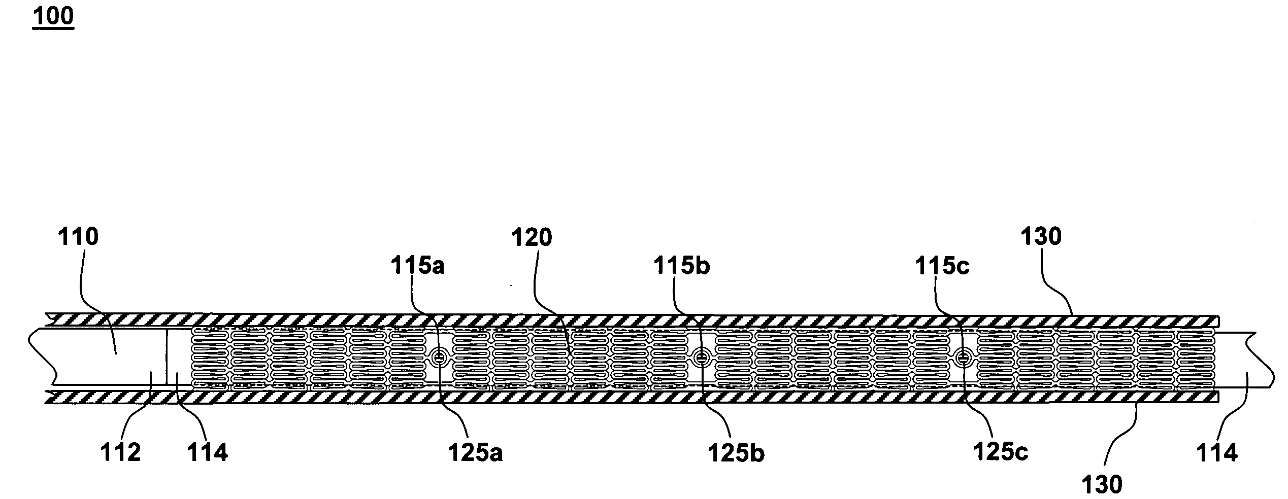
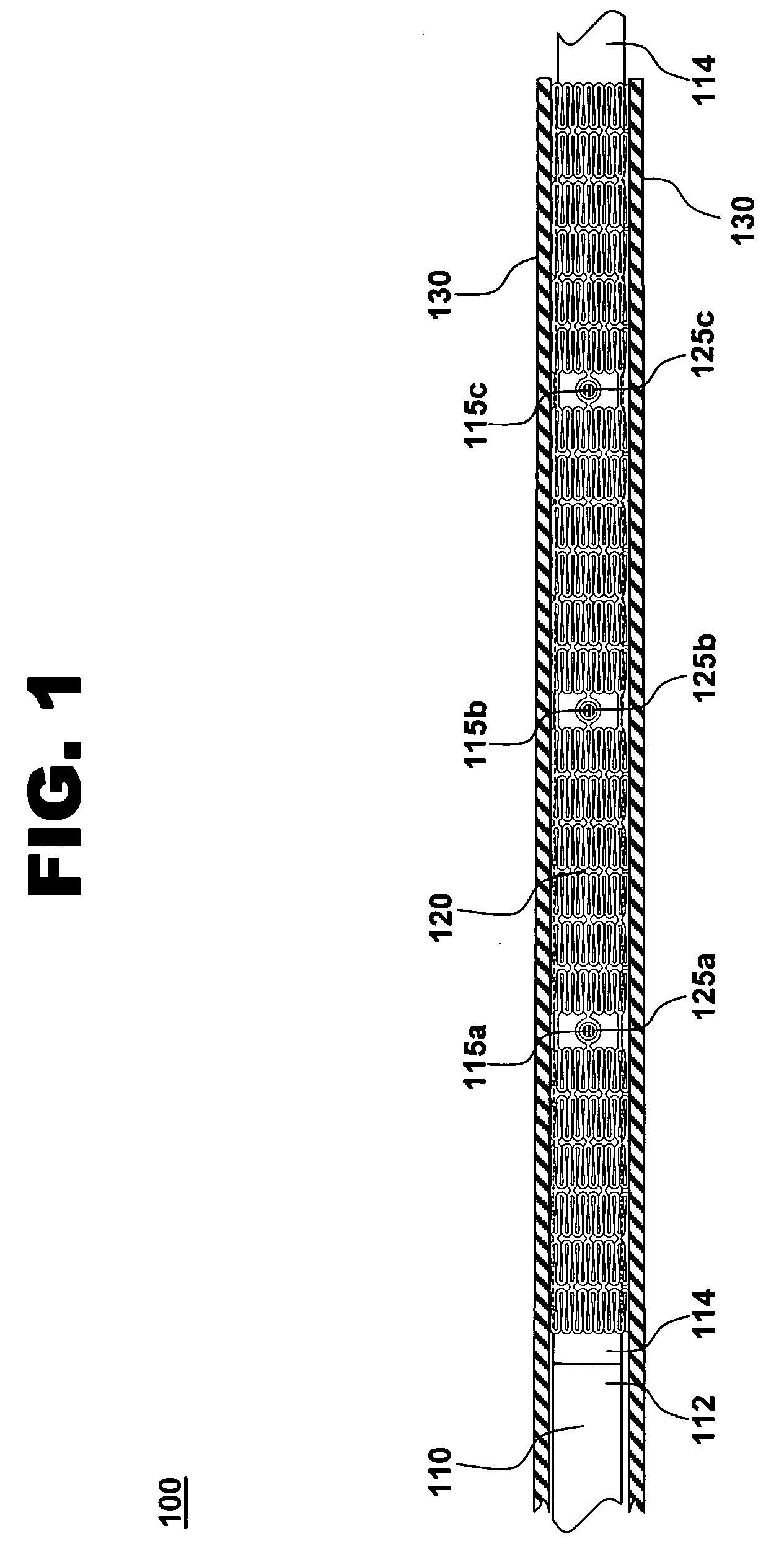
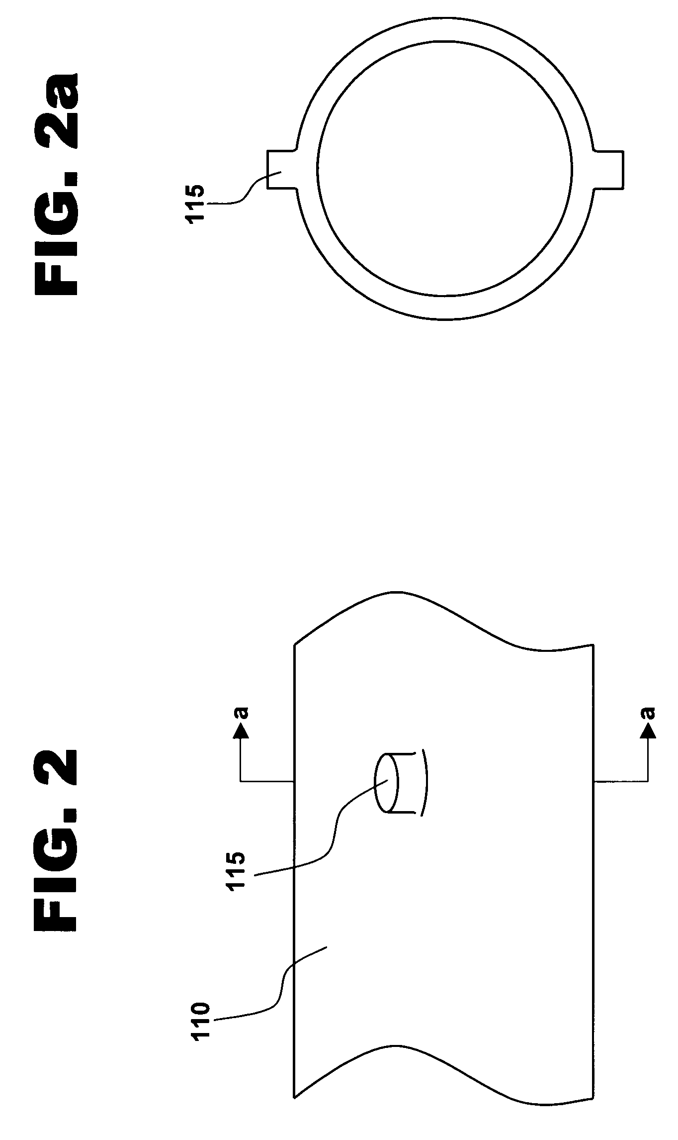
[0021] One aspect according to the present invention is a system for treating a vascular condition. One embodiment of the system, in accordance with the present invention, is illustrated at 100 in FIG. 1. The system comprises a catheter inner member 110, a stent 120, and a sheath 130. Inner member 110 has a proximal portion 112 and a distal portion 114, with longitudinally spaced protrusions 115a,b,c, extending from the outer surface of distal portion 114. Stent 120 includes a plurality of longitudinally spaced apertures 125a,b,c, formed in the wall of the stent. Sheath 130 is shown in cross-section to reveal inner member 110 and stent 120 within. Only a distal portion of system 100 is illustrated. As used herein, the terms “distal” and “proximal” are with reference to the treating clinician during deployment of the stent.

[0022] Inner member 110 is an elongated structure that, in the present embodiment, includes a central lumen through which a guidewire may pass. Inner member 110 i...


PUM


Abstract

The invention provides a system that distributes along the length of a stent those forces exerted on the stent during release of the stent from a sheath. The system includes a catheter inner member, a stent, and a sheath. Multiple longitudinally spaced protrusions extend from the outer surface of a distal portion of the inner member. Complementary longitudinally spaced apertures are formed in the wall of the stent. The stent is mounted on the inner member with the inner member protrusions received within the stent apertures. The sheath encloses the stent and is movable with respect to the stent. The system is assembled by aligning the protrusions and apertures and radially compressing the stent about the inner member. The resulting interlocked protrusions and apertures allow the stent to be withdrawn from a radial compression device into the sheath by pulling on the inner member.

Description

TECHNICAL FIELD [0001] This invention relates generally to biomedical systems for treating vascular conditions and to methods for manufacturing and using such biomedical systems. More specifically, the invention relates to a stent delivery system that distributes along the length of a stent, forces exerted on the stent during release of the stent from a sheath and to methods for assembling and using such a system. BACKGROUND OF THE INVENTION [0002] Stents are cylindrical devices that are radially expandable to hold open a segment of a vessel or other anatomical lumen after deployment in the lumen. Various types of stents are in use, including balloon expandable and self-expanding stents. Balloon expandable stents generally are conveyed to the area to be treated on balloon catheters. A self-expanding stent is conveyed to a treatment site while compressed within a sheath. Once positioned, the sheath is retracted, allowing expansion of the stent. [0003] Before deployment of the self-ex...

Claims


Application Information

Patent Timeline
Patent Type & Authority Applications(United States)
IPC IPC(8): A61F2/06
CPCA61F2/91A61F2/915A61F2/95A61F2002/91508A61F2002/91541A61F2002/91558A61F2002/9583A61F2002/9665
Inventor PRYOR, JACK
Owner MEDTRONIC VASCULAR INC
Why Eureka
Try Eureka