Percutaneous spinal implants and methods

a technology of spinal implants and implants, applied in spinal implants, medical science, surgery, etc., can solve the problems of increased risk of significant complications, loss of bladder or bowel function, or paralysis,

Inactive Publication Date: 2006-08-17
KYPHON
View PDF99 Cites 348 Cited by
  • Summary
  • Abstract
  • Description
  • Claims
  • Application Information

AI Technical Summary

Problems solved by technology

Spinal stenosis can cause pain, weakness, numbness, burning sensations, tingling, and in particularly severe cases, may cause loss of bladder or bowel function, or paralysis.
This procedure, however, may result in blood loss and an increased chance of significant complications, and usually results in an extended hospital stay.
Such known procedures, however, may not be suitable in conditions where the spinous processes are severely compressed.
Moreover, such procedures typically involve large or multiple incisions.

Method used


Image

  • Percutaneous spinal implants and methods
  • Percutaneous spinal implants and methods
  • Percutaneous spinal implants and methods

Examples


Embodiment Construction

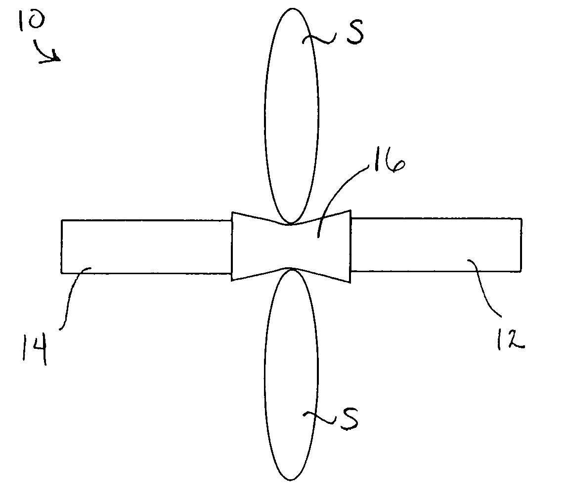
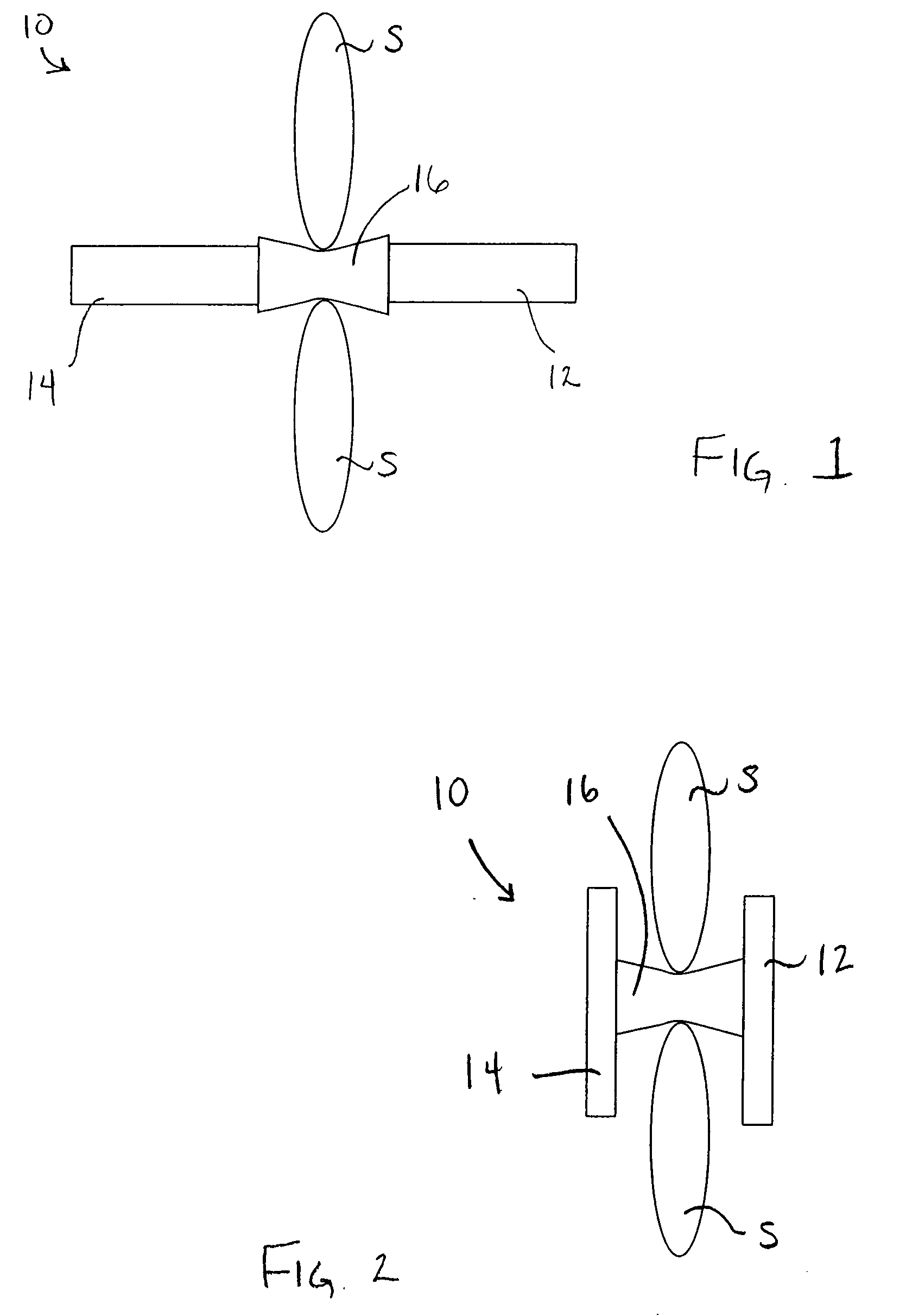
[0040] An apparatus includes an elongate member having a proximal portion configured to be deformed from a first configuration to a second configuration under, for example, an axial load or a radial load. The elongate member has a distal portion configured to be deformed from a first configuration to a second configuration under, for example, an axial load or a radial load. A central portion is positioned between the proximal portion and the distal portion. The central portion is configured to engage adjacent spinous processes.

[0041] In some embodiments of the invention, the elongate member can have multiple portions that each move from a first configuration to a second configuration, either simultaneously or serially. Additionally, the device, or portions thereof, can be in many positions during the movement from the first configuration to the second configuration. For ease of reference, the entire device is referred to as being in either a first configuration or a second configur...


PUM


Abstract

An apparatus includes a guide shaft, an expansion member coupled to the guide shaft, and an actuator. The expansion member is configured to impart a force from within an interior of an implant to deform the implant. The actuator is coupled to the expansion member, the actuator is configured to move the expansion member from a first position to a second position.

Description

CROSS-REFERENCE TO RELATED APPLICATIONS [0001] This application is a continuation-in-part of U.S. patent application Ser. No. 11 / 059,526, entitled “Apparatus and Method for Treatment of Spinal Conditions,” filed Feb. 17, 2005 and also claims the benefit of U.S. Provisional Application Ser. No. 60 / 695,836 entitled “Percutaneous Spinal Implants and Methods,” filed Jul. 1, 2005, each of which is incorporated herein by reference in its entirety.BACKGROUND [0002] The invention relates generally to percutaneous spinal implants, and more particularly, to percutaneous spinal implants for implantation between adjacent spinous processes. [0003] A back condition that impacts many individuals is spinal stenosis. Spinal stenosis is a progressive narrowing of the spinal canal that causes compression of the spinal cord. Each vertebra in the spinal column has an opening that extends through it. The openings are aligned vertically to form the spinal canal. The spinal cord runs through the spinal can...

Claims


Application Information

Patent Timeline
Patent Type & Authority Applications(United States)
IPC IPC(8): A61F2/44
CPCA61B17/025A61B17/7062A61B17/7065A61B2017/00557A61B2017/0256
Inventor EDIDIN, AVRAM ALLANMALANDAIN, HUGUES F.
Owner KYPHON
Why Eureka
Try Eureka