Parts packaging device and parts packaging method

a technology of parts packaging and components, which is applied in the direction of metal working apparatus, printed circuit manufacturing, manufacturing tools, etc., can solve the problems of essentially solving the above problem, unable to reduce the time itself required for flux supply, and unable so as to reduce the time required for component mounting of a plurality of components, the effect of efficient component mounting

Inactive Publication Date: 2006-08-24
PANASONIC CORP
View PDF4 Cites 40 Cited by
  • Summary
  • Abstract
  • Description
  • Claims
  • Application Information

AI Technical Summary

Benefits of technology

[0058] According to the eighth aspect of the invention, after the supply of the bonding-assistant agent to the first component among the plurality of components is performed, and before the mounting of the bonding-assistant agent-supplied first component onto the board is completed, the supply of the bonding-assistant agent to the second component among the plurality of components is started. By virtue of this, the mounting operation of the first component onto the board, and the supply operation of the bonding-assistant agent to the second component to be next mounted onto the board, can be carried out in parallel to each other. Accordingly, whereas the conventional component mounting method has had an issue that the supply operation of the bonding-assistant agent to the second component cannot be performed during the mounting operation of the first component so that the time required for supply operation of the bonding-assistant agent has been an obstacle to reduction in the time required for component mounting operation, it beco

Problems solved by technology

However, with the component mounting apparatus 501 of the structure described above, since the time required for the mounting head section 511, which has the component 503 delivered from the inversion head section 521 at the component delivery position L, to mount the component 503 onto the board 502 includes the time required for the flux supply to the component 503, th

Method used


Image

  • Parts packaging device and parts packaging method
  • Parts packaging device and parts packaging method
  • Parts packaging device and parts packaging method

Examples


Embodiment Construction

[0090] Before the description of the present invention proceeds, it is to be noted that like parts are designated by like reference numerals throughout the accompanying drawings.

[0091] Hereinbelow, one embodiment of the present invention is described in detail with reference to the accompanying drawings.

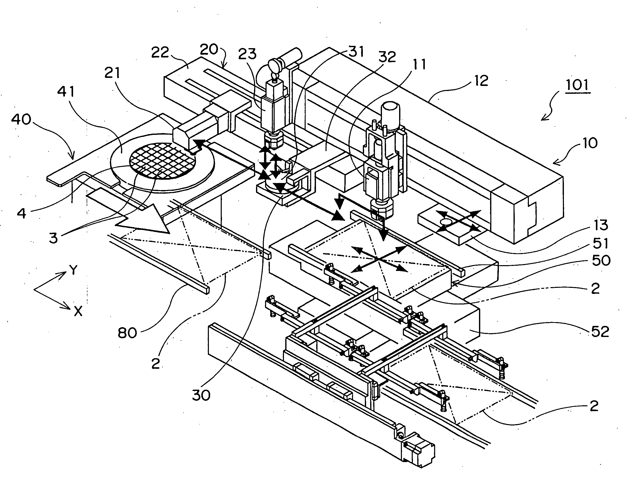
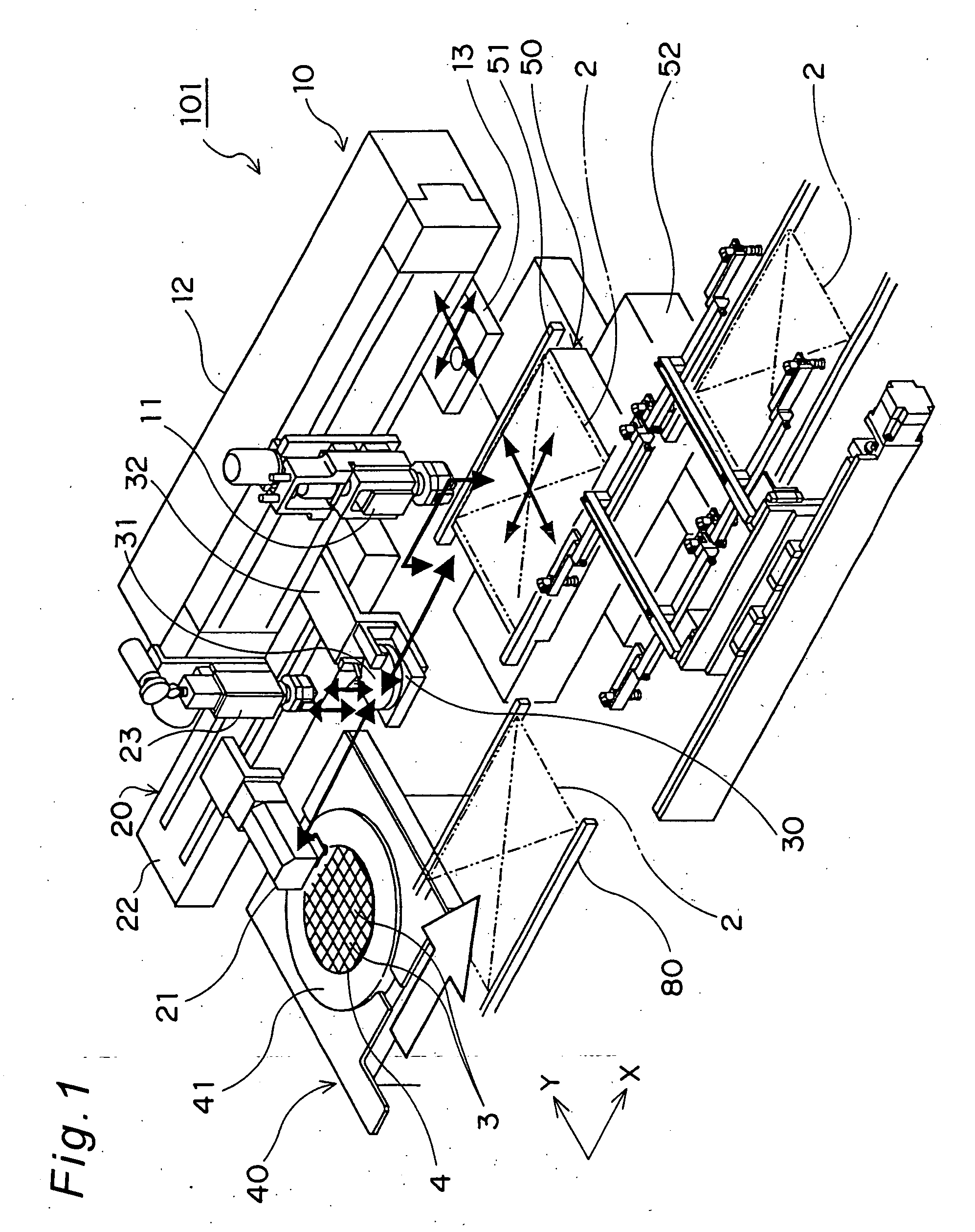
[0092] A schematic perspective view showing main constituent members of a component mounting apparatus 101 which is an example of the component mounting apparatus according to an embodiment of the invention is shown in FIG. 1.

[0093] As shown in FIG. 1, the component mounting apparatus 101 is a component mounting apparatus for mounting, for example, a bare IC chip or other like component 3 onto a board 2, the component mounting apparatus including a mounting head unit 10 for holding and mounting the component 3 onto the board 2, a board holding unit 50 for releasably holding the board 2, a component feed unit 40 for extractably housing a plurality of components 3, and a transfer un...


PUM

PropertyMeasurementUnit
Timeaaaaaaaaaa
Thicknessaaaaaaaaaa

Abstract

In component mounting process for a plurality of components to be mounted onto a board, a plurality of bump electrode portions formed on mounting-side surfaces of the components to be mounted onto the board are brought into contact with a bonding-assistant agent so that the bonding-assistant agent is supplied thereto to allow the bonding-assistant agent-supplied components to be mounted onto the board, the component mounting process includes, supplying the bonding-assistant agent to a first component among the plurality of components, and starting the supply of the bonding-assistant agent to a second component among the plurality of components before completion of the mounting of the bonding-assistant agent-supplied first component onto the board.

Description

BACKGROUND OF THE INVENTION [0001] The present invention relates to a component mounting apparatus and a component mounting method for mounting a plurality of components onto a circuit board, in which device or method a bonding-assistant agent is supplied to the components by making a plurality of bump electrodes brought into contact with the bonding-assistant agent, the bump electrodes being formed on mounting-side surfaces of the components on which side the components are to be mounted onto the board, and the bonding-assistant agent serving as an auxiliary agent for bonding in the mounting of the components onto the board, where the components supplied with the bonding-assistant agent are mounted onto the circuit board via the respective bump electrodes. [0002] Conventionally, as this kind of component mounting apparatus and component mounting method, those of various structures have been known (see, e.g., Japanese unexamined patent publication No. H09-82748). As an example of su...

Claims


Application Information

Patent Timeline
IPC IPC(8): H05K3/34B23P19/00H01L21/00H05K13/04
CPCH01L21/67144H05K13/046H01L24/75H01L24/81H01L2224/16225Y10T29/4913Y10T29/53174Y10T29/49149Y10T29/53187Y10T29/53178Y10T29/49151Y10T29/53183Y10T29/49144H01L2924/00011H01L2924/00014H01L2924/14H01L2924/00H01L2224/0401H05K13/04
Inventor SHIDA, SATOSHIKANAYAMA, SHINJIONOBORI, SHUNJIHIRATA, SHUICHINAKAO, MAMORUOE, KUNIOKUGIHARA, AKIRANARITA, SHORIKIETOH, YOSHITAKAHAJI, HIROSHI
Owner PANASONIC CORP
Why Eureka
Try Eureka