Method and apparatus for printing a web

a web and web technology, applied in the field of methods and printing equipment, can solve the problems of high complication and expenditure, only suitable printing machines of the kind, and achieve the effect of quick conversion

Inactive Publication Date: 2006-08-24
STEFFEN VOLKER +2
View PDF12 Cites 0 Cited by
  • Summary
  • Abstract
  • Description
  • Claims
  • Application Information

AI Technical Summary

Benefits of technology

[0009] An object of the present invention is to provide a method of printing on a web such that when making a transition from one print image to another it is possible to convert quickly to the new image format.
[0010] Another object of the invention is to provide a method of printing on material in web form, which permits accurate guidance and positioning of the web of material for the purposes of achieving a high level of quality of the print images produced on the web.
[0011] Still another object of the invention is to provide a method of printing a web of material which can afford a sufficiently high through-put capacity to satisfy at least the demands usually made nowadays.

Problems solved by technology

A disadvantage with such a machine however is that, when changing from one print image to another, it is necessary to replace at least the transfer cylinder if the subsequent print image is of a different length because that then requires a transfer cylinder of a different diameter.
That entails a correspondingly high level of complication and expenditure, especially as conversion of the machine in that way also requires a certain amount of time.
For that reason printing machines of that kind are only suitable for producing large numbers of the same print image.

Method used


Image

  • Method and apparatus for printing a web
  • Method and apparatus for printing a web
  • Method and apparatus for printing a web

Examples


Embodiment Construction

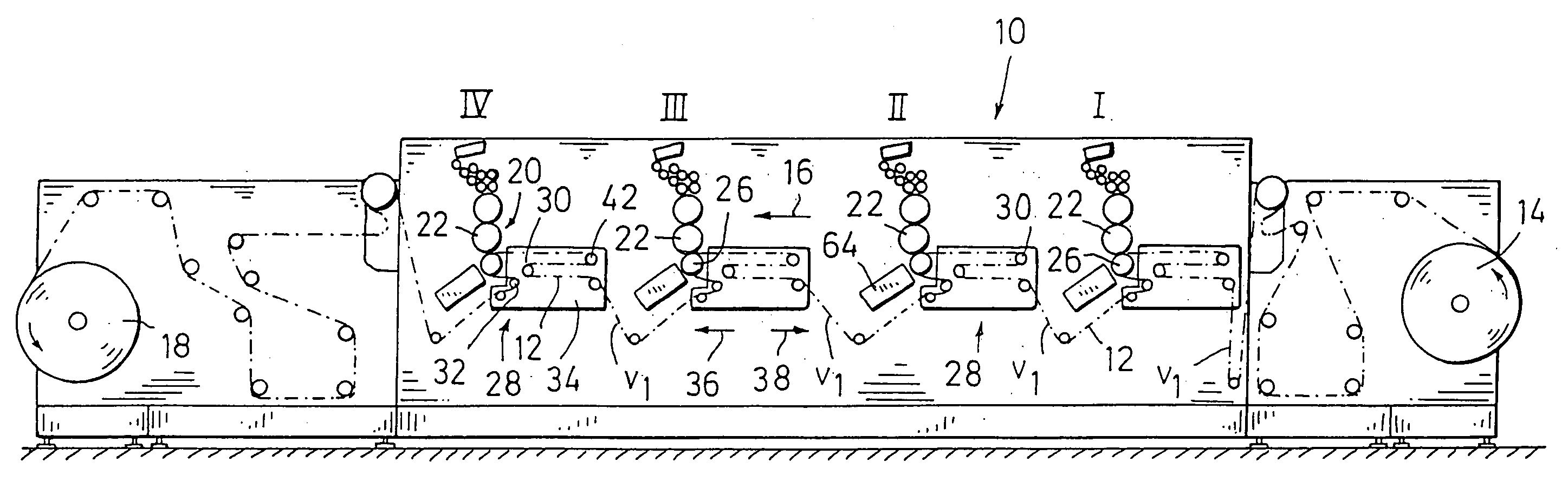
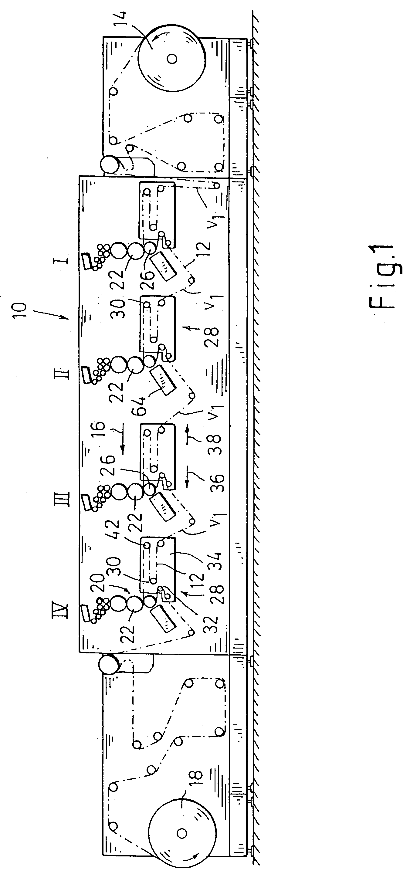
[0025] Referring firstly to FIG. 1, shown therein is a printing machine 10 for printing on material in web form, as generally indicated at 12, which is drawn off a first roll 14 and passed in a general transportation direction indicated by an arrow 16 through first through fourth printing stations I-IV arranged in succession in the transportation direction 16. The printing stations are each of substantially the same structure. After the complete printing operation has been effected by the web 12 passing through the printing stations the web 12 is then wound on to a second roll 18.

[0026] Each printing station I-IV is provided with a printing mechanism which is generally indicated by reference numeral 20 in the printing station IV, and devices for transporting, positioning and guiding the web 12 to be printed upon, in the region of the respective printing station. The web passes into each respective printing station at a constant intake speed indicated at V1.

[0027] In the embodiment...


PUM


Abstract

In a method and an apparatus for printing on material in web form print images are successively applied to the web by a transfer cylinder. The web is continuously drawn into the printing station and the speed at which the web is moved in the printing station during a printing operation is greater than the speed at which it is drawn into the printing station. After the printing operation the web is positioned in the printing station for the following printing operation relative to the transfer cylinder which is not in contact with the web during a part of a revolution of 360.degree., and at the same time the path of the web is altered in accordance with the change in the speed thereof. The web is driven by the impression cylinder which is associated with the transfer cylinder and around the peripheral surface of which the web partially passes. Positioning of the web for the respectively following printing operation is implemented by a change in the rotary movement of the impression cylinder.

Description

[0001] CROSS-REFERENCE TO RELATED APPLICATIONS [0002] This application is a divisional application of U.S. patent application Ser. No. 10 / 456,225, filed on Jun. 6, 2003.FIELD OF THE INVENTION [0003] The invention concerns a method and an apparatus for printing material in web form. [0004] In this specification the term print image is used to denote a print image applied to a web of material, which may be a complete print image in itself, or alternatively a partial print image such that a plurality of such partial print images are applied to the web of material at the same location in order thereby to produce an overall print image, as is the case for example with multi-color printing. [0005] Furthermore in this specification the term printing is intended to include any printing and decorating processes such as relief printing, for example flexographic printing, intaglio printing and rotary screen printing, but also stamping or embossing, in particular hot stamping or embossing, with...

Claims


Application Information

Patent Timeline
Patent Type & Authority Applications(United States)
IPC IPC(8): B41F13/54B41F23/04B41F13/02B41F13/04B41F13/14B65H23/188
CPCY10S101/42B41F13/04
Inventor STEFFEN, VOLKERSCHNEIDER, HELMUTSCHULZ, MATHIAS
Owner STEFFEN VOLKER
Why Eureka
Try Eureka