Spatial prediction based intra-coding

a prediction and spatial technology, applied in the field of image coding, can solve the problems reducing the transmission rate, and rendering real-time image transmission impossible, and achieving the effect of reducing the prediction tabl

Inactive Publication Date: 2006-08-24
KARCZEWICZ MARTA
View PDF4 Cites 31 Cited by
  • Summary
  • Abstract
  • Description
  • Claims
  • Application Information

AI Technical Summary

Benefits of technology

The present invention aims to reduce the prediction table used in image coding systems by eliminating prediction elements through the use of table symmetry. This will lead to a more efficient and effective coding process.

Problems solved by technology

The technical problem addressed in this patent text is how to efficiently encode a digital image without requiring excessive memory usage and sacrificing accuracy.

Method used


Image

  • Spatial prediction based intra-coding
  • Spatial prediction based intra-coding
  • Spatial prediction based intra-coding

Examples


Embodiment Construction

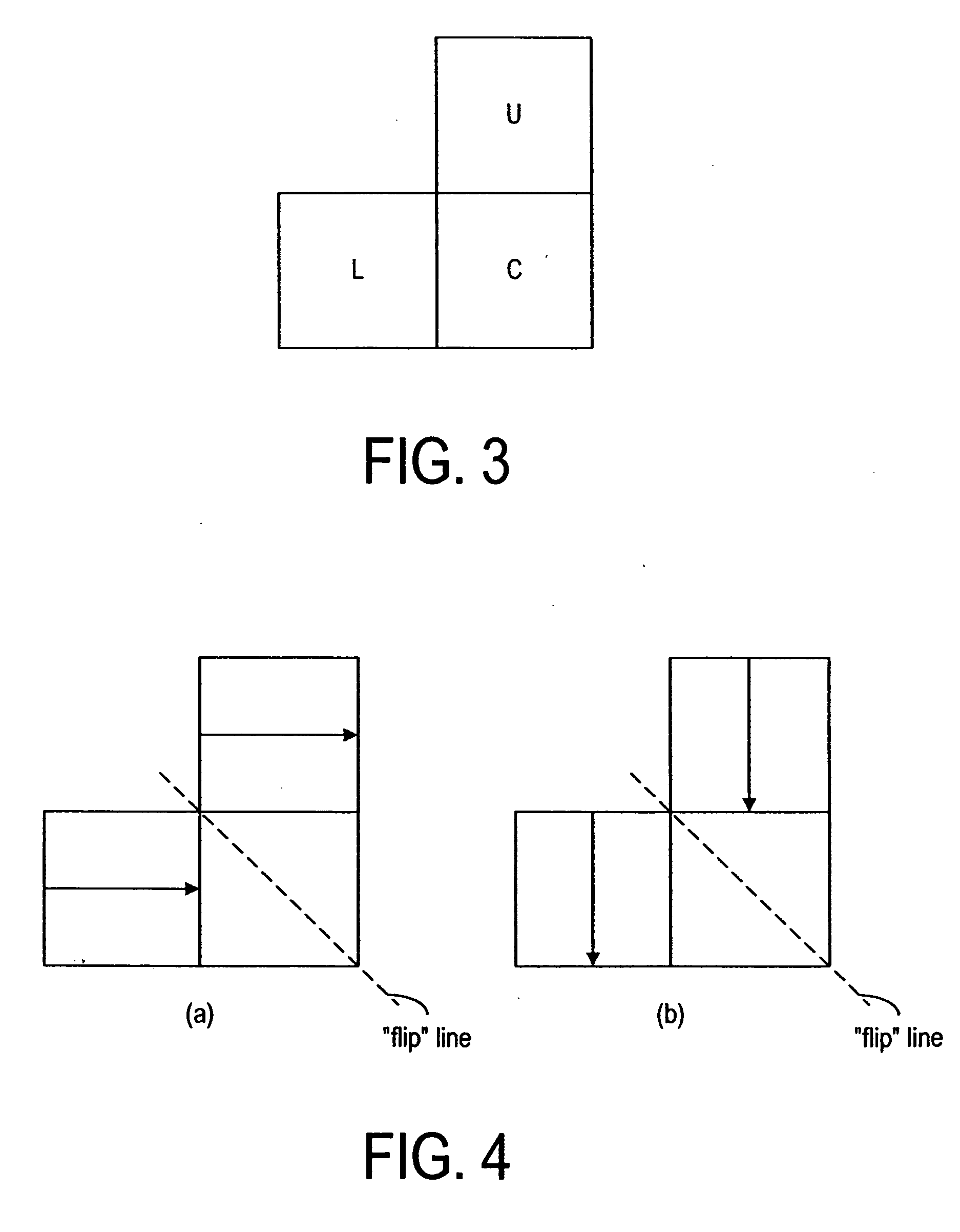
[0078] The present invention utilizes the property that it should be possible to obtain an ordered list of prediction modes for one combination of prediction modes of neighboring blocks as a function of prediction modes for another combination. For illustration purposes, prediction modes of two neighboring blocks U and L, as shown in FIG. 4a, are used to infer the prediction of the current block C. It is noted that a combination of prediction modes in FIG. 4a can be obtained by flipping diagonally the prediction modes, as shown in FIG. 4b. Accordingly, the nth most probable prediction mode for block C, when the combination of modes in FIG. 4a is used, should be the same as the “flipped diagonally”, nth-most-probable prediction mode for the combination of modes in FIG. 4b. Thus, if the neighboring blocks U and L have the modes “vertical” and “vertical”, the prediction mode of the current block C is most probably “vertical” (FIG. 4b). Consequently, when these blocks are “flipped” or m...


PUM


Abstract

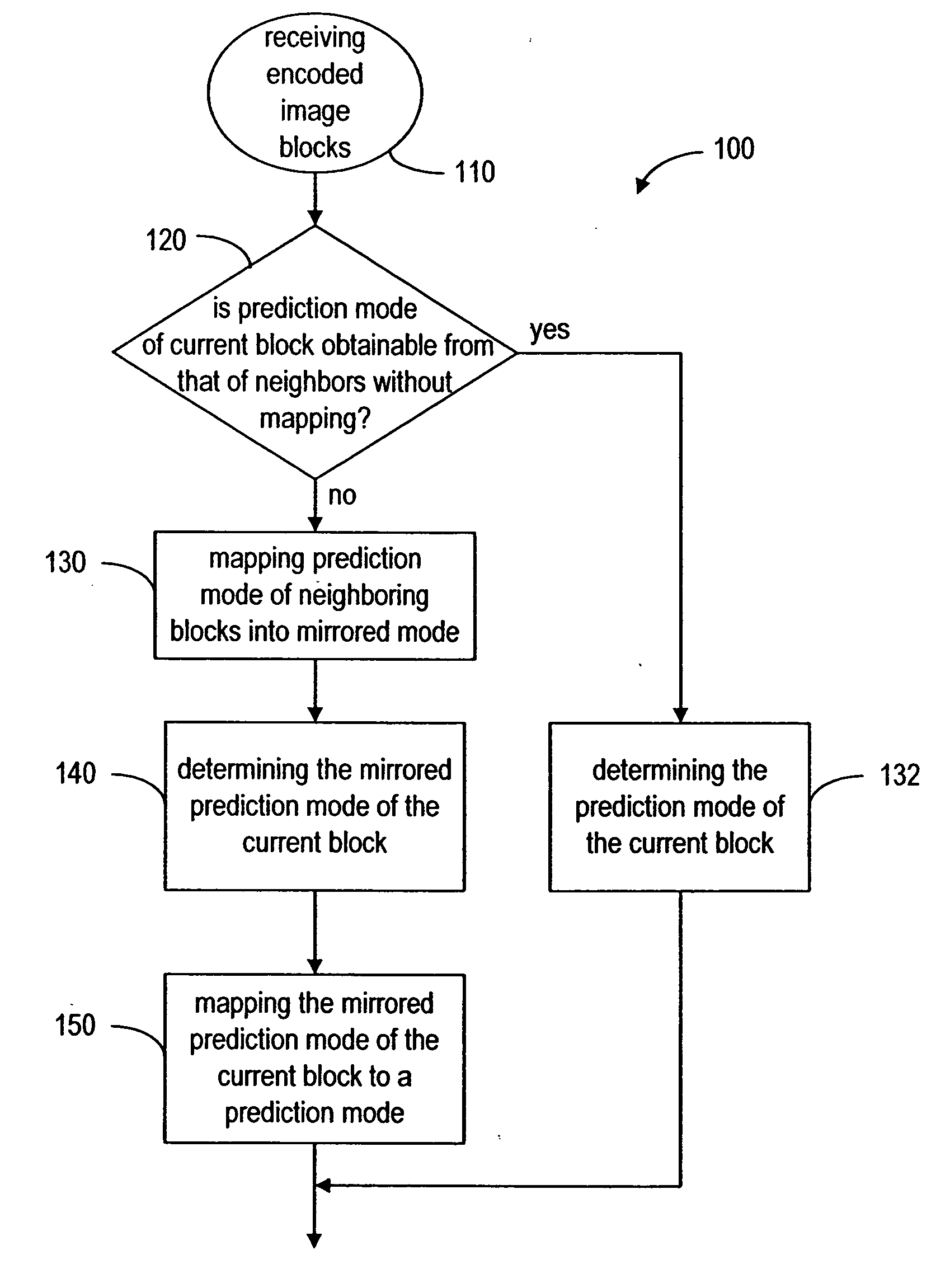
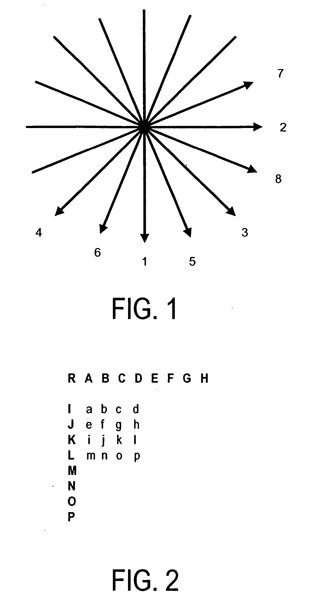
A method and device for coding a digital image using intra-mode block prediction, wherein the prediction mode of a current block is obtained from the prediction mode of the neighboring blocks. Using the property that it is possible to obtain an ordered list of prediction modes for one combination of prediction modes of the neighboring blocks as a function of the prediction modes for another combination, the size of the prediction table to be used in the encoding and decoding stages can be reduced. Furthermore, in the case of JVT coder, some of the prediction modes can be grouped together and the prediction modes can be relabeled in order to reduce the number of prediction modes.

Description


Claims


Application Information

Patent Timeline
Owner KARCZEWICZ MARTA
Why Eureka
Try Eureka