Radio frequency switch device

Inactive Publication Date: 2006-08-24
SAMSUNG ELECTRONICS CO LTD
View PDF2 Cites 0 Cited by
  • Summary
  • Abstract
  • Description
  • Claims
  • Application Information

AI Technical Summary

Benefits of technology

[0018] Accordingly, the present invention has been made to solve the above-mentioned problems occurring in the prior art and provides additional advantag

Problems solved by technology

A conventional radio frequency switch, as shown in FIG. 1, is not suitable to control many DAS in groups with a small space and a minimum expense.
Mechanical switches have good insertion losses and good insulation properties, but have a disadvantage in that their size is large.
On the other hand, radio frequency switches that use semiconductor devices have an advantage in that their size is quite small, but have disadvantages in that insertion losses and insulation properties are not good.
However, in a case the mechanical radio frequency switch is applied to the RoF, the volume of the resultant device is relatively large in comparison with the number of DAS that can control one radio frequency switch.
However, since the conventional radio frequency switch includes expensive parts such as the SMA connecters, the SMA adapters, and the SMA cables to co

Method used


Image

  • Radio frequency switch device
  • Radio frequency switch device
  • Radio frequency switch device

Examples


Embodiment Construction

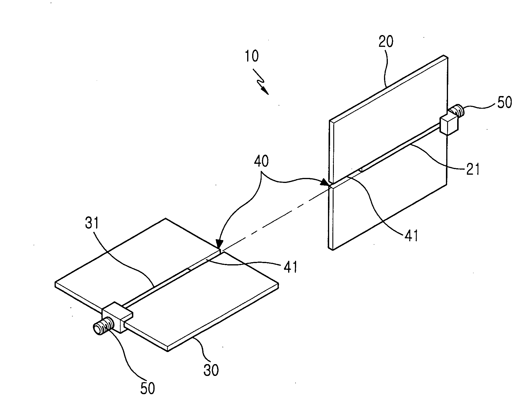
[0032] Hereinafter, embodiments of the present invention will be described with reference to the accompanying drawings.

[0033] As shown in FIGS. 3 and 4, a radio frequency switch 10 according to the present invention includes a plurality of first substrates 20, a plurality of second substrates 30, and a combining means 40. The first substrate 20 forms a ground surface. A micro-strip line 21 and a semiconductor on / off switch (not shown) are disposed on a flat surface of the ground surface thereof. The second substrate 30 also forms a second ground surface, and micro-strip line 31 is disposed on a flat surface of the ground surface thereof. The second substrate 30 is combined with the first substrate 20 so as to be substantially orthogonal to, or cross, and are electrically connected to each other. The combining means 40 is formed so as to allow first and second substrates 20 and 30 to cross each other.

[0034]FIG. 5 illustrates a plane view of an exemplary substrate representative of ...


PUM


Abstract

A radio frequency switch is disclosed. The switch includes a plurality of first substrates in which a ground surface is formed on each of the first substrates and a micro-strip line and a semiconductor on/off switch are disposed on a plane surface of the ground surface, a plurality of second substrates in which a ground surface is formed on each of the second substrates and a micro-strip line is disposed on a plan surface of the ground surface, the second substrates being combined with the first substrates so as to cross each other and being electrically connected to the first substrates, and combining means for combining the first and second substrates so as to cross each other.

Description

CLAIM OF PRIORITY [0001] This application claims the benefit of the early filing date pursuant to 35 USC §119 to that patent application entitled “Radio Frequency Switch Device,” filed in the Korean Industrial Property Office on Feb. 21, 2005 and assigned Ser. No. 2005-14183, the contents of which are hereby incorporated by reference. BACKGROUND OF THE INVENTION [0002] 1. Field of the Invention [0003] The present invention relates to a switching device and more specifically to a radio frequency switch device that includes substrates assembled while crossing each other. [0004] 2. Description of the Related Art [0005] As frequency resources are restricted and users demand various multimedia services, base stations employ optical cables having broadband characteristics, excellent frequency characteristics, and low loss characteristics to provide such multimedia services. Base stations may also use distributed antenna systems (hereinafter, referred to as DAS) which are now being develop...

Claims


Application Information

Patent Timeline
IPC IPC(8): H04B1/38H04M1/00
CPCH01P1/127H01P1/15H04Q1/149
Inventor HWANG, SEONG-TAEKLEE, JAE-HOONKIM, MOON-ILJEONG, JI-CHAISON, JONG-KUCK
Owner SAMSUNG ELECTRONICS CO LTD
Why Eureka
Try Eureka