Percussion instrument

a technology of percussion instruments and tension bolts, which is applied in the direction of percussion instruments, musical instruments, and musical instruments, can solve the problems of difficulty in adjusting the clamping force of the plurality of tension bolts, and achieve the reduction of the component and manufacturing cost of the belt member, the design is small, and the design is easy to be simplified

Active Publication Date: 2012-01-05
ROLAND CORP
View PDF1 Cites 0 Cited by
  • Summary
  • Abstract
  • Description
  • Claims
  • Application Information

AI Technical Summary

Benefits of technology

[0005]In a percussion instrument according to an example embodiment of the present invention, a belt member is made to vibrate upon being struck on a striking surface of the belt member. In this embodiment, the belt member is formed in a band shape from an elastic material and is stretched between stretching members that are supported on a frame. The belt member has a tensile force that manifests a sinking and rebounding action of the striking surface, upon the belt member being struck. Therefore, the same tension sensation as that of an acoustic percussion instrument is reproduced and simulated. In addition, the dimensions of the striking surface in the width direction may be made relatively small, as compared to the case in which the striking surface is configured in a circular shape. Accordingly, the overall size of the percussion instrument can be reduced or minimized, thus, making it possible to utilize a reduced or minimized space to set up the percussion instrument for use. In addition, because the striking surface can be made relatively small, the striking sound generated upon striking the striking surface can be made relatively small, as compared to the case in which the striking surface is configured in a circular shape.
[0016]In a further example of a percussion instrument according to embodiments that include a linking buffering member as described above, because vibrations of the belt member that are produced when the belt member is struck are quickly attenuated by the buffering member, acoustic noise that is produced at the time that the belt member has been struck can be suppressed. In addition, the linking buffering member may be arranged to link to mutually facing sides of the inner peripheral surfaces of the belt member. In such embodiments, the construction of the frame can be simplified and reduced in cost by not including the linking buffering member on the frame.

Problems solved by technology

With such configurations, it can be difficult to adjust the clamping force of the plurality of tension bolts and uniformly adjust the tensile force in the radial direction of the head.

Method used


Image

  • Percussion instrument
  • Percussion instrument
  • Percussion instrument

Examples


Embodiment Construction

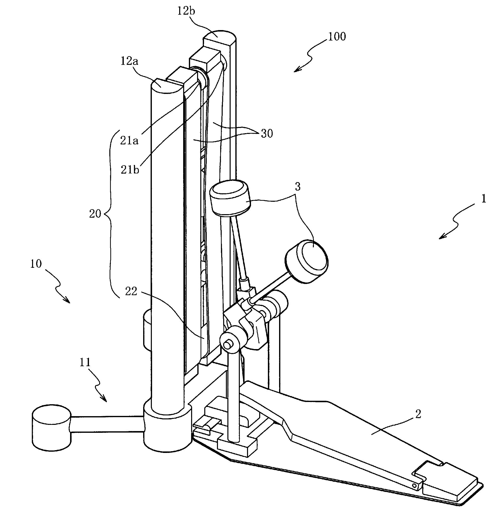
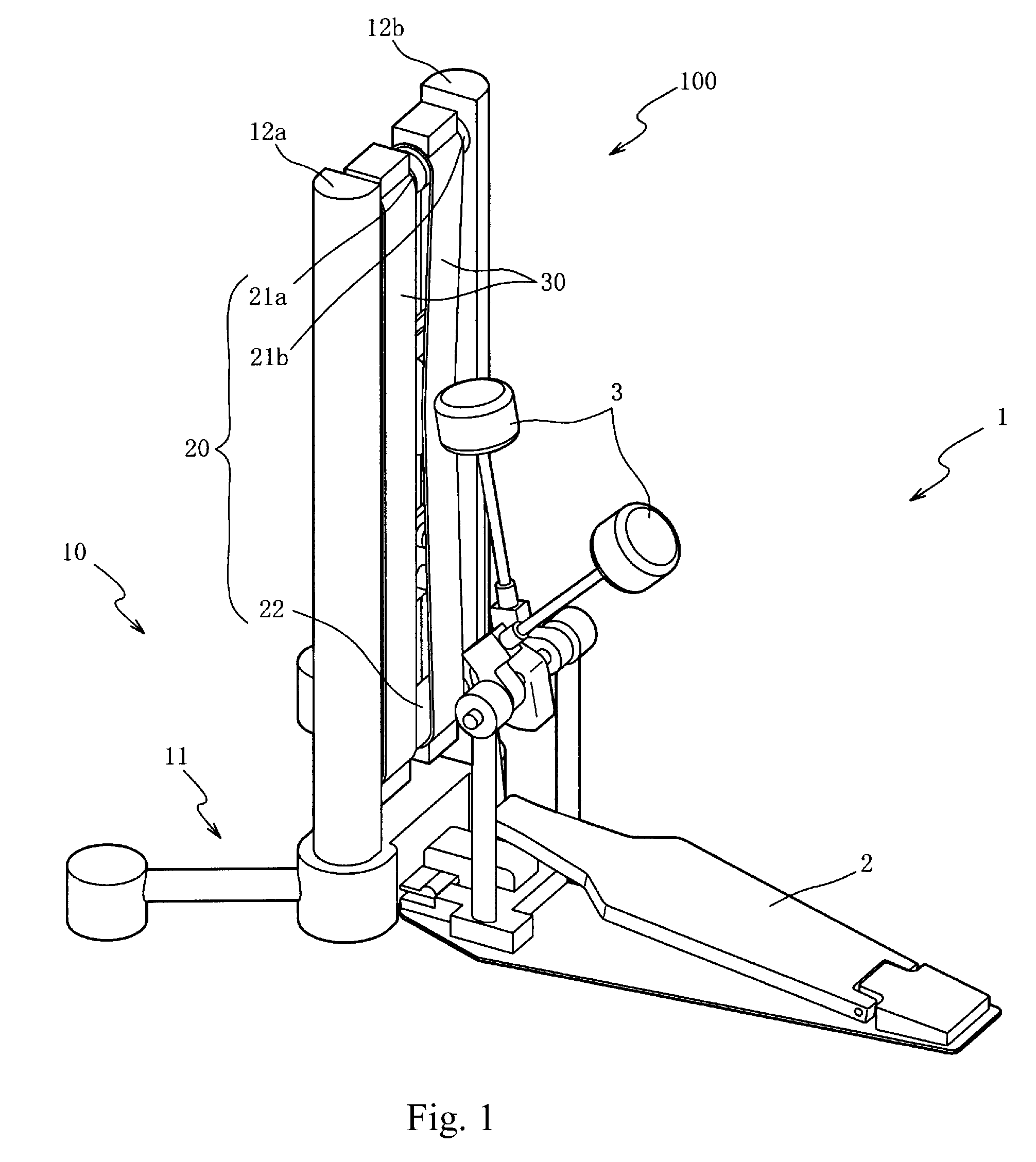
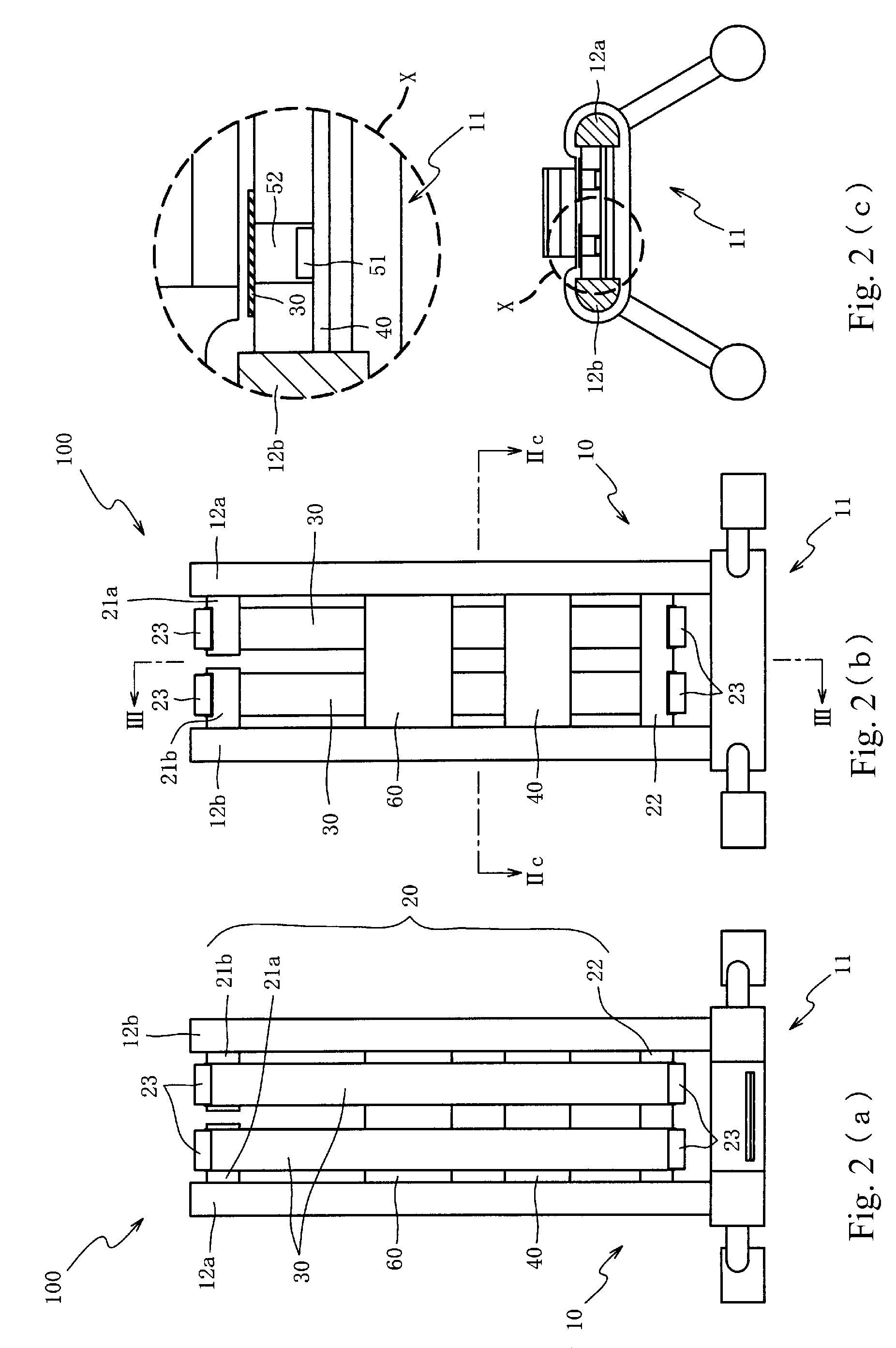
[0030]An explanation will be given below regarding preferred embodiments of the present invention while referring to the attached drawings. First, an explanation will be given regarding the configuration of an electronic percussion instrument 100 of FIG. 1, in according to a first embodiment. FIG. 2(a) is a front view of the electronic percussion instrument 100. FIG. 2(b) is a rear view of the electronic percussion instrument 100. FIG. 2(c) is a cross section view of the electronic percussion instrument 100 along the line IIc-IIc of FIG. 2(b). FIG. 3(a) is a cross section view of the electronic percussion instrument 100 along the line III-III of FIG. 2(b). FIG. 3(b) is a cross section view of the electronic percussion instrument 100 along the line III-III of FIG. 2(b) at the time at which the belt member 30 is struck. In FIG. 1, the foot pedal apparatus 1 is shown in a state in which it has been mounted on the electronic percussion instrument 100. For simplifying the drawing of FIG....


PUM


Abstract

A percussion instrument is configured for minimizing space used for set up for use. The percussion instrument uses a belt member stretched between one of two upper stretching members and a lower stretching member, to form a striking surface. By using the elasticity of the belt member, the striking surface can simulate the tension sensation of a conventional acoustic percussion instrument. By forming the belt member in a band shape, the width dimensions of the striking surface can be small relative to conventional circular shaped striking surfaces.

Description

CROSS-REFERENCE TO RELATED PATENT APPLICATIONS[0001]Japan Priority Application 2010-152508, filed Jul. 2, 2010 including the specification, drawings, claims and abstract, is incorporated herein by reference in its entirety.FIELD OF THE INVENTION[0002]The present invention relates to a percussion instrument and, in particular embodiments, to a percussion instrument that utilizes a relatively small space for setup.BACKGROUND[0003]An example of a percussion instruments that simulates an acoustic bass drum is disclosed in Japanese Laid-Open Patent Application Publication (Kokai) Number H11-212566. The instrument described in that patent reference has a head 3 that is configured from a net form material arranged over an opening end of a cylindrical shell 1. As a result, the acoustic striking sound when the head 3 is struck is suppressed, while vibrations of the head 3 are detected by the striking sensor 4. In the above-described percussion instrument, the shell 1 is formed roughly in a c...

Claims


Application Information

Patent Timeline
Patent Type & Authority Applications(United States)
IPC IPC(8): G10D13/02
CPCG10D13/006G10D13/029G10D13/024G10D13/26G10D13/02G10D13/11G10D13/03
Inventor YOSHINO, KIYOSHI
Owner ROLAND CORP
Why Eureka
Try Eureka