Vessel propulsion apparatus

a technology for propulsion apparatus and engine, which is applied in the direction of marine propulsion, vessel construction, combustion air/fuel air treatment, etc., can solve the problems conflicting demands of increasing the size of the engine and downsizing the engine cowling, and piping may wear or be damaged, so as to minimize or prevent the increase in the total size of the number and size of the structural elements included in the engine cowling, the effect of increasing the total size of the number and

Active Publication Date: 2016-06-21
YAMAHA MOTOR CO LTD
View PDF11 Cites 0 Cited by
  • Summary
  • Abstract
  • Description
  • Claims
  • Application Information

AI Technical Summary

Benefits of technology

[0009]The bracket holds wiring or piping (hereinafter, referred to as “wiring or the like”) by the holding portion provided in the coupling portion that couples the first mounting portion and the second mounting portion each other. That is, the bracket not only mounts the auxiliary machinery on the engine main body, but also holds the wiring or the like. Thus, as compared with a case of providing a bracket for the wiring or the like in addition to a bracket for the auxiliary machinery, the number and size of the structural elements that are housed inside the engine cowling are reduced. The engine cowling is thus downsized. Further, even if the engine main body is increased in size, an increase in the size and number of structural elements included in the engine cowling is minimized or prevented, so that an increase in the size of the engine cowling is minimized or prevented.
[0026]According to this configuration of a preferred embodiment of the present invention, the holding portion of the bracket is disposed in a gap in the horizontal direction between the engine main body and the starter motor. The space in the horizontal direction between the engine main body and the starter motor is thus used as a space to dispose the holding portion. Further, the holding portion of the bracket is disposed in a gap in the up-down direction between the engine main body and the ring gear. Thus, the space in the up-down direction between the engine main body and the ring gear is also used as a space to dispose the holding portion. In this manner, because the space between the engine main body and the auxiliary machinery is effectively used, the number and size of structural elements included in the engine cowling is significantly reduced or minimized. Accordingly, an increase in a total size of the number and size of structural elements included in the engine cowling is minimized or prevented. An increase in the size of the engine cowling is thus minimized or prevented.

Problems solved by technology

In some other cases, it is demanded to increase the power of the outboard motor that will lead to an increase in the size of the engine.
Thus, conflicting demands of an increase in the size of the engine and downsizing of the engine cowling are sometimes made.
In this configuration, when the cowling is downsized, the piping may wear or be damaged due to sliding of the cowling and piping, because the inner surface of the cowling approaches the piping.
Therefore, it is difficult to downsize the cowling.
In particular, when the engine main body is increased in size, the piping approaches the inner surface of the cowling, so that it is more difficult to downsize the cowling.
In some situations, an increase in the size of the engine cowling is thus required.

Method used


Image

  • Vessel propulsion apparatus
  • Vessel propulsion apparatus
  • Vessel propulsion apparatus

Examples


Embodiment Construction

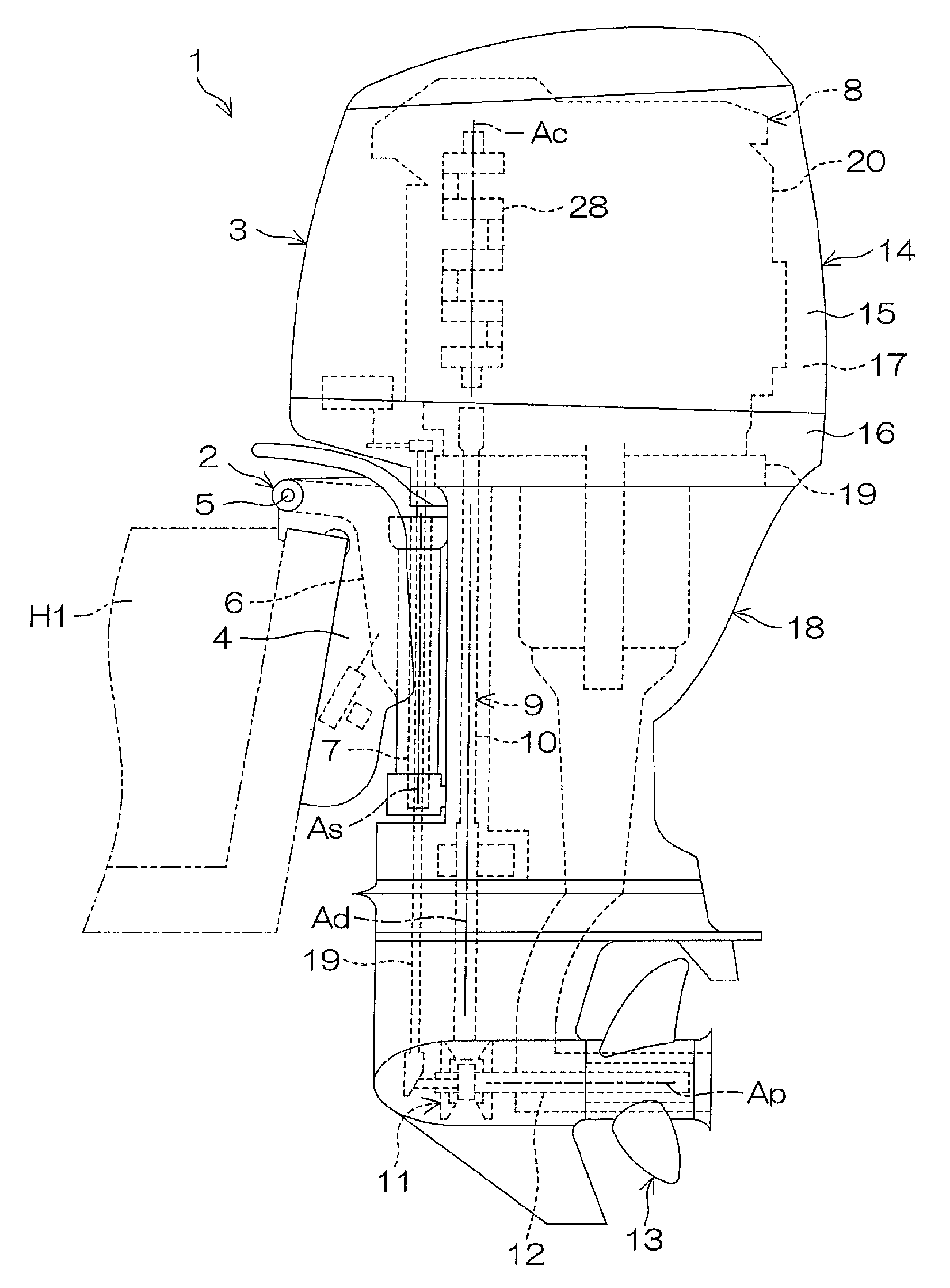
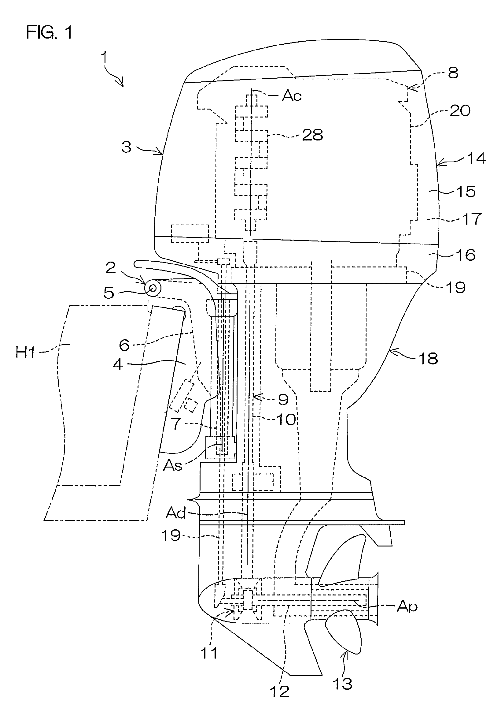
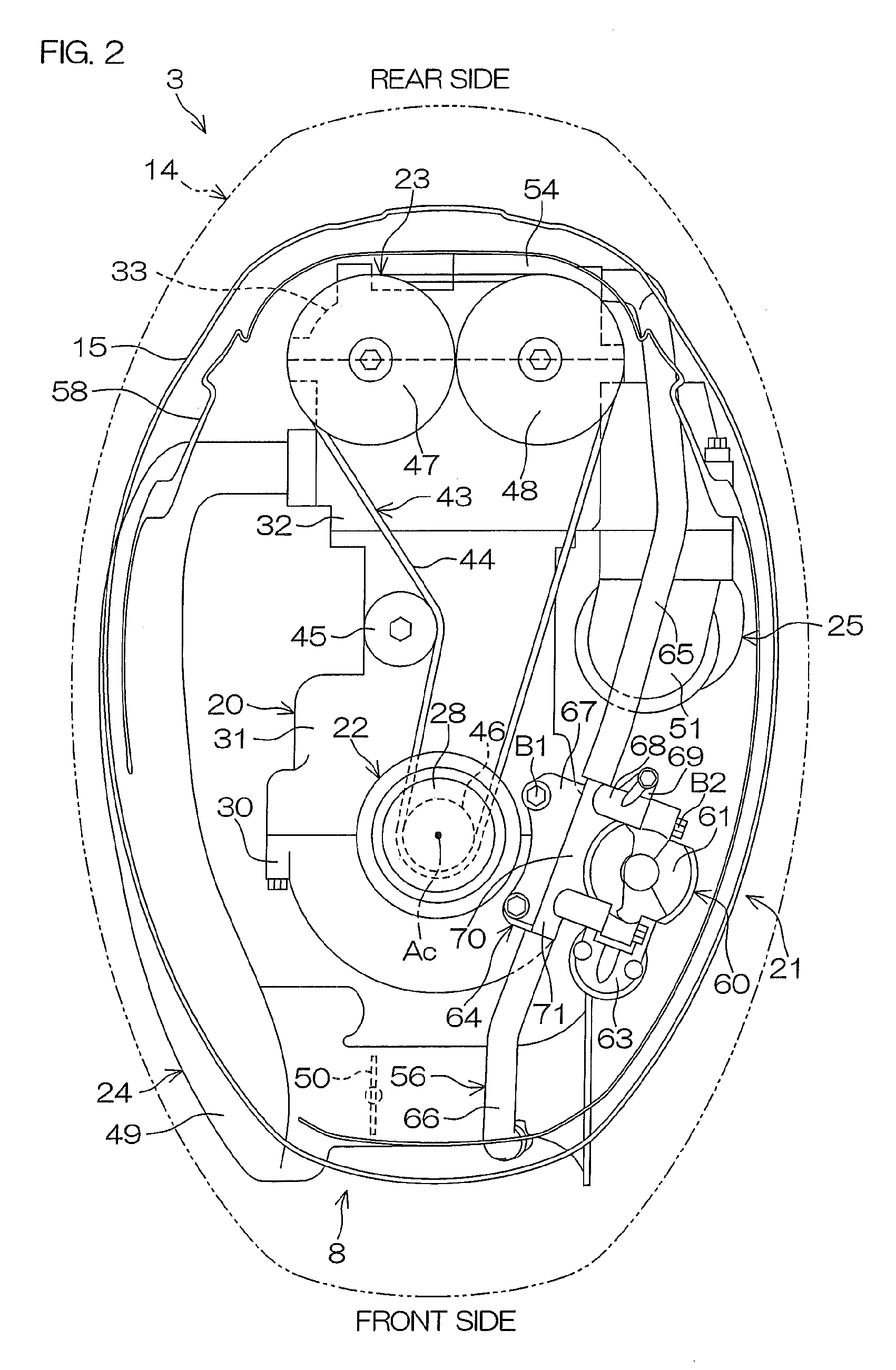
[0044]FIG. 1 is a schematic side view showing a vessel propulsion apparatus 1 according to a first preferred embodiment of the present invention. FIG. 2 is a schematic plan view showing an engine 8. FIG. 3 is a schematic sectional view showing a schematic configuration of the engine 8. FIG. 2 shows a cross-section when a top cover 15 portion of an engine cowling 14 and an inner cover 58 are cut horizontally at a height equal to a mounting position of an engine main body 20 and a bracket 64 by solid lines, and shows an outer contour of the engine cowling 14 when an outboard motor 3 is observed from above by a long and two short dashed line. Further, FIG. 2 shows a state in which a flywheel 57 has been removed.

[0045]As shown in FIG. 1, the vessel propulsion apparatus 1 includes a suspension apparatus 2 mountable on a rear portion (stern) of a hull H1 and an outboard motor 3 coupled to the suspension apparatus 2.

[0046]As shown in FIG. 1, the suspension apparatus 2 includes a pair of le...


PUM


Abstract

A vessel propulsion apparatus includes an engine main body including a crankshaft that is rotatable about a rotation axis extending in the up-down direction, auxiliary machinery mounted on the engine main body, a bracket that couples the auxiliary machinery to the engine main body, and an engine cowling that houses the engine main body, the auxiliary machinery, and the bracket. The bracket includes a first mounting portion mounted on the engine main body, a second mounting portion mounted on the auxiliary machinery, a coupling portion coupling the first mounting portion and the second mounting portion, and a holding portion provided in the coupling portion. The holding portion of the bracket holds piping.

Description

BACKGROUND OF THE INVENTION[0001]1. Field of the Invention[0002]The present invention relates to a vessel propulsion apparatus.[0003]2. Description of the Related Art[0004]Outboard motors include engines that generate power and engine cowlings that house the engines. Wiring and piping are disposed in the interior of the engine cowlings. For example, Japanese Patent Application Publication No. 2010-25004 discloses piping 100 that is disposed in a cowling. As shown in FIG. 12, the piping 100 extends from a silencer case 131 of an intake system 130 to the vicinity of a pulley 123 passing by the left side of a flywheel 125.[0005]In the outboard motor, downsizing of the engine cowling that houses the engine is demanded in some cases. In some other cases, it is demanded to increase the power of the outboard motor that will lead to an increase in the size of the engine. Thus, conflicting demands of an increase in the size of the engine and downsizing of the engine cowling are sometimes mad...

Claims


Application Information

Patent Timeline
Patent Type & Authority Patents(United States)
IPC IPC(8): B63H20/20B63H20/32B63H20/00B63H20/24F02M35/16
CPCB63H20/32B63H20/20B63H21/265B63H20/245B63H20/24F02M35/167
Inventor NAKAMURA, RYOU
Owner YAMAHA MOTOR CO LTD
Why Eureka
Try Eureka