Anti-removal ratchet clip

a ratchet clip and anti-removal technology, applied in the field of ratcheting clips or locks, can solve the problems of ratcheting clips cease to be fastened and the ratcheting clips become disengaged, and achieve the effect of reducing risks

Active Publication Date: 2006-08-31
ILLINOIS TOOL WORKS INC
View PDF6 Cites 12 Cited by
  • Summary
  • Abstract
  • Description
  • Claims
  • Application Information

AI Technical Summary

Benefits of technology

[0004] The present invention is directed to a ratcheting clip that includes a male end and a female end. When the male end is inserted into the female end, a retaining wall on the male end interfaces with a track on the female end. The interface of the track and the retaining wall prevents lateral forces from causing either the female or the male end to move relative to the other. The interface between the track and the retaining wall also prevents either of the ends from being lifted up. Thus, the interface between the track and the retaining wall helps prevent the ratcheting clip from becoming disengaged. Accordingly, once the ratcheting clip is installed on an object, there is a reduced risk that inadvertent contact with the ratcheting clip will cause it to become disengaged from the object. In an exemplary embodiment, the ratcheting clip can include one or more secondary clips configured to support or mount to other objects.

Problems solved by technology

Another problem is that an outwardly directed force exerted on the second end can cause the second end to lift away from the first end so that the teeth become disengaged and the ratcheting clip ceases to be fastened to the desired object.

Method used


Image

  • Anti-removal ratchet clip
  • Anti-removal ratchet clip
  • Anti-removal ratchet clip

Examples


Embodiment Construction

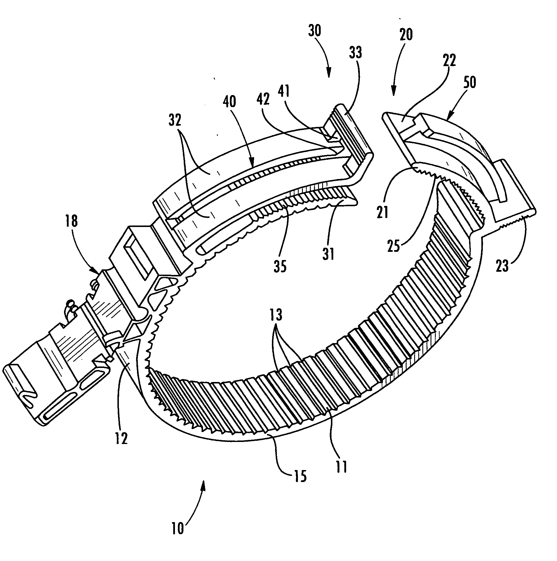
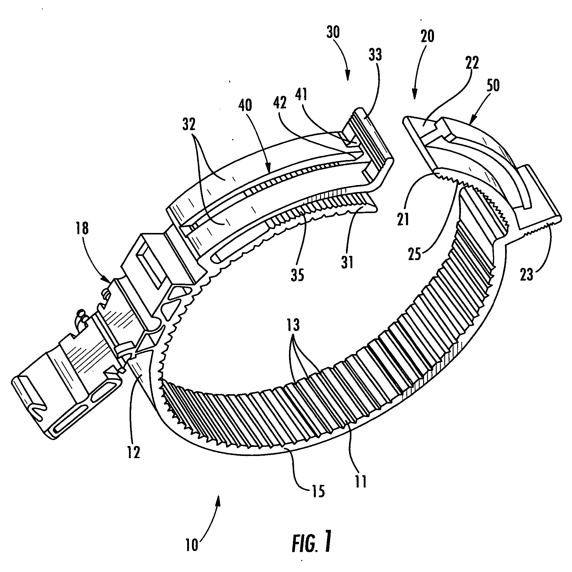
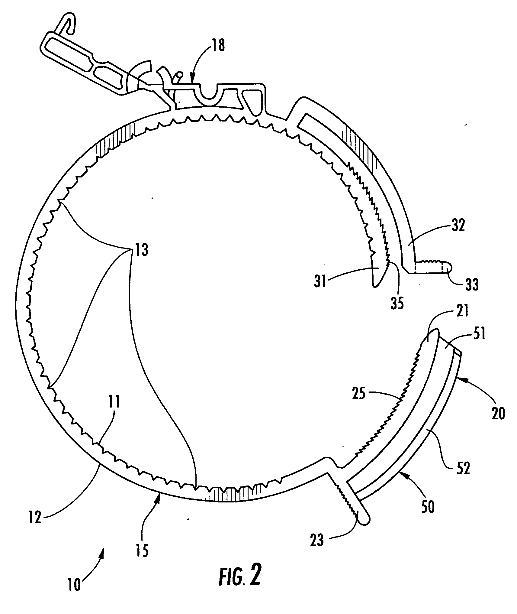
[0016] Referring to FIGS. 1 and 2, an exemplary embodiment of a ratcheting clip 10 of the invention is depicted. The ratcheting clip 10 can be made of various types of material such as nylon 6 / 6, and if a plastic such as nylon 6 / 6 is used, it can include fillers such as glass fibers as desired. Thus, depending on the needed properties of the ratcheting clip 10, the materials used to make the ratcheting clip can be varied. As is known in the art, ratcheting clips such as the ratcheting clip 10 can be made using a known molding process.

[0017] As depicted, the ratcheting clip 10 includes a first clip 18 for use in supporting an object. The ratcheting clip 10 could be provided with other types of clips as desired. In an alternative embodiment, the ratcheting clip 10 could be provided without the first clip 18.

[0018] As illustrated in FIGS. 1 and 2, the ratcheting clip 10 includes an inner surface 11 and an outer surface 12. To allow the ratcheting clip 10 to close in a desired manner,...


PUM


Abstract

A ratcheting clip includes a center section, a male end and a female end, the female end having a top half and a bottom half. The male end is configured to be inserted into the female end between the top and bottom half so that opposing sets of teeth hold the male end and female end together. To prevent inadvertent disengagement of the opposing sets of teeth, the male end includes a retaining surface that is configured to interface with a track disposed in the top half of the female end. Once the male end is inserted into the female end, the interface between the retaining surface and the track prevents lateral forces from causing one end to move in a lateral direction with respect to the other end. The interface between the retaining surface and the track further prevents the top half from being lifted upward away from the male end.

Description

FIELD OF THE INVENTION [0001] The present invention relates generally to ratcheting clips or locks and more particularly to a feature on a ratcheting clip that inhibits removal of the ratcheting clip. BACKGROUND OF THE INVENTION [0002] It is known to use ratcheting clips to mount objects together, particularly cylindrical objects. Ratcheting clips have been used to aid in mounting and positioning of tubing and wire bundles but can also be used to mount a first object, such as a brake line, a piece of tubing or a wire bundle, to a second object, such as a second piece of tubing or a drive shaft. Typically, the ratcheting clip is configured to mount to a particular range of diameters and includes a first and a second end. The first and second ends are configured to mate so as to allow the ratcheting clip to mount to the surface of the object, such as an outer diameter of a section of tubing. Typically, the two ends are configured to overlap when the ratcheting clip is installed. The f...

Claims


Application Information

Patent Timeline
Patent Type & Authority Applications(United States)
IPC IPC(8): B65D63/00
CPCF16L3/137Y10T24/14Y10T24/1498F16L3/233
Inventor PEARSON, TIMOTHY D.SHEREYK, DAVID A.
Owner ILLINOIS TOOL WORKS INC
Why Eureka
Try Eureka