Method of welding a component inside a hollow vessel

a hollow vessel and component technology, applied in the field of welding, can solve the problems of increasing the total number of parts and the overall cost of the fuel tank assembly, and not being able to meet the requirements of the fuel tank

Active Publication Date: 2006-08-31
DENSO INTERNATIONAL AMERICA
View PDF21 Cites 12 Cited by
  • Summary
  • Abstract
  • Description
  • Claims
  • Application Information

AI Technical Summary

Problems solved by technology

In such situations, these traditionally metal components are attached to an interior surface of the fuel tank using traditional fasteners such as bolts or screws that pass through holes in the tank wall, and may necessitate holes in the components themselves.
While this method of fastening components to a wall of the fuel tank has generally served its purpose, it has not been without its share of limitations.
For instance, using fasteners to attach components to the interior surface of the fuel tank necessitates the use of bolts, screws or other fasteners, which adds to the total number of parts and the overall cost of the fuel tank assembly.
Additionally, using traditional fasteners to mount internal fuel tank components results in the drilling of holes in the fuel tank through which the fasteners must pass to secure the component to the tank wall.
Another disadvantage of securing components with traditional fasteners is that mounting components with traditional fasteners means that the connection is not permanent and may be a source of noise, vibration and harshness.
Yet another disadvantage is that securing components within a fuel tank using traditional fasteners takes multiple fastening steps thereby increasing the time necessary to fasten such components.

Method used


Image

  • Method of welding a component inside a hollow vessel
  • Method of welding a component inside a hollow vessel
  • Method of welding a component inside a hollow vessel

Examples


Embodiment Construction

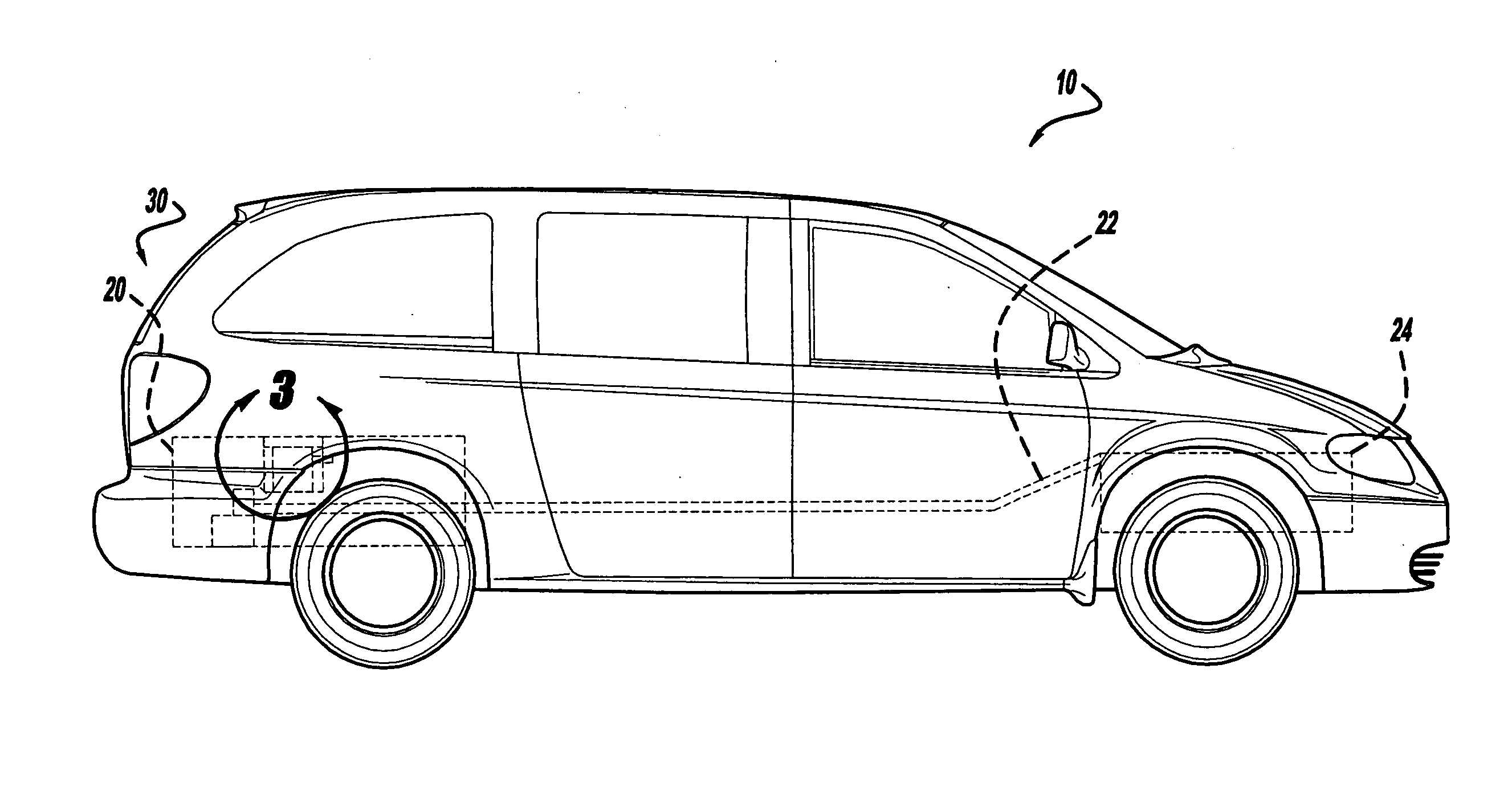
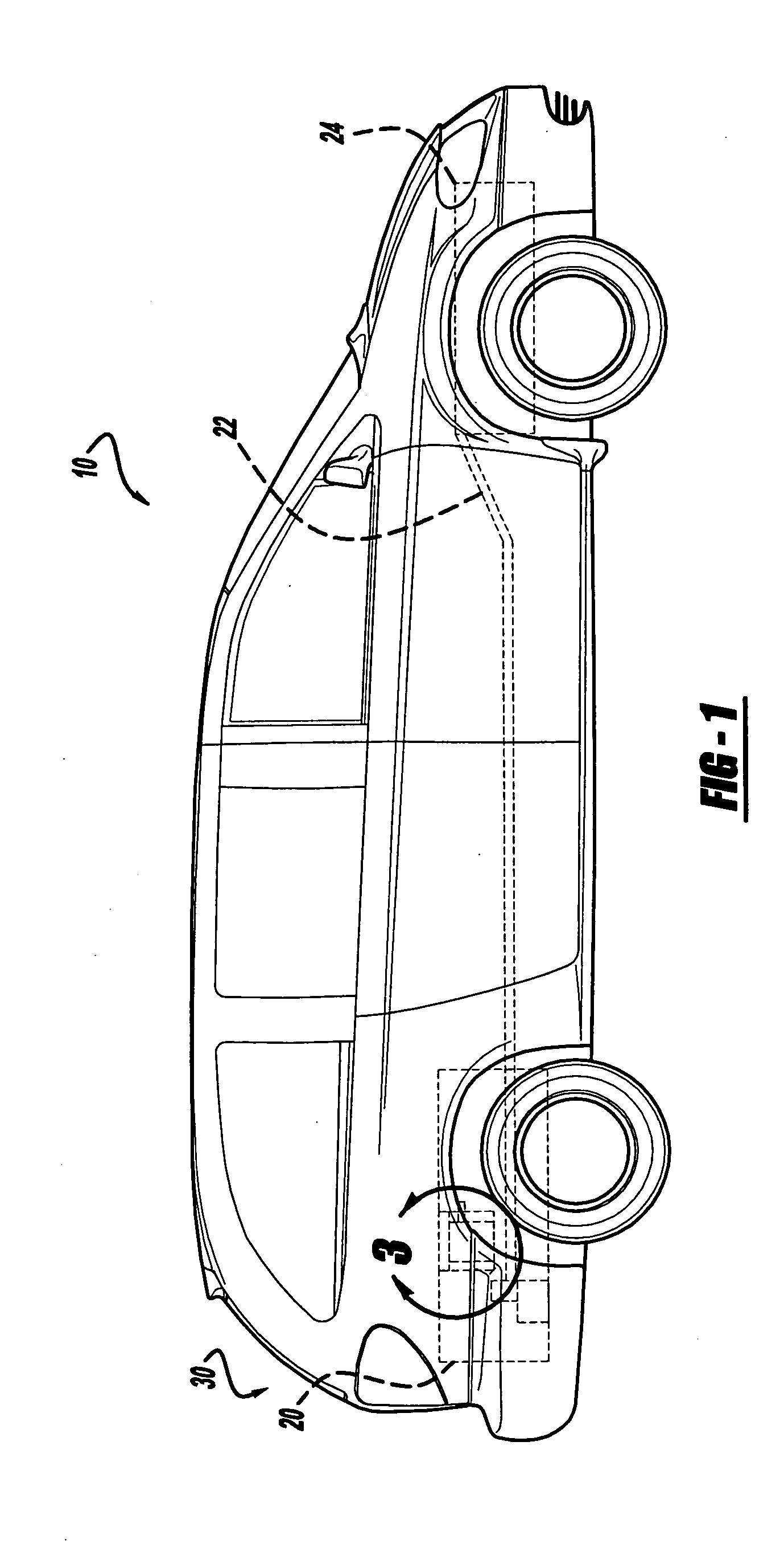
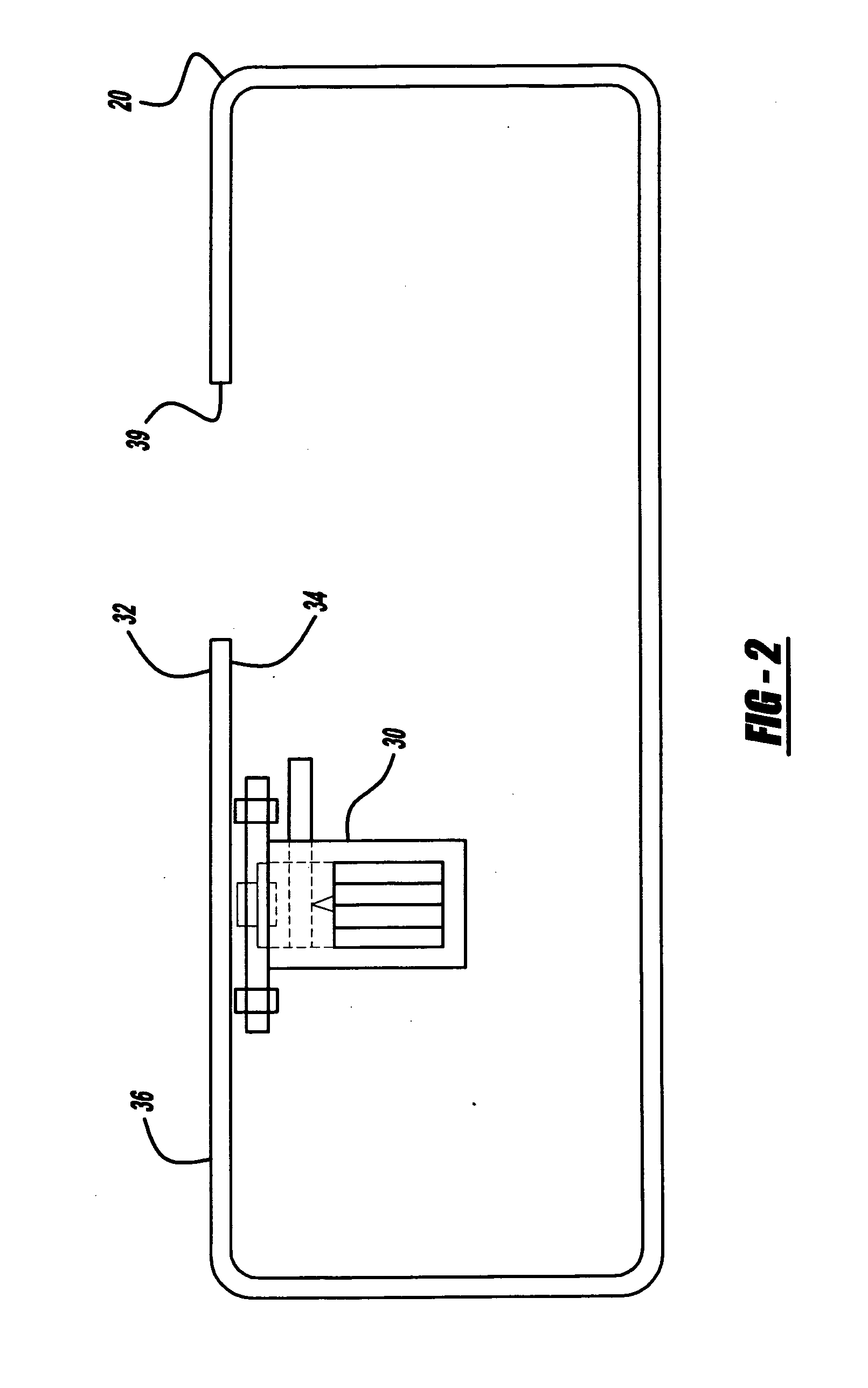
[0018] The following description of the preferred embodiments is merely exemplary in nature and is in no way intended to limit the invention, its application, or uses. With reference to FIGS. 1 through 8, a method of welding a component inside a hollow vessel via induction heating in accordance with the teachings of the present invention will be described. The welding method of the teachings of the present invention is primarily for welding plastic components together. For example, for welding a first plastic component to a second plastic component. Normally the type or kind of plastic of the two components is the same in order to facilitate consistent bonding of the parts. However, the type of plastic does not necessarily have to be the same, but rather only compatible in order to provide a proper weld. Compatibility of the two plastics will also depend upon the bond material, that is, the induction weld plastic material that will be used to join the parts together. As long as the ...


PUM

PropertyMeasurementUnit
temperatureaaaaaaaaaa
timeaaaaaaaaaa
induction weldableaaaaaaaaaa

Abstract

A method of welding plastic components using an induction weldable plastic material to a wall of a hollow plastic vessel entails providing a metal disk to a first plastic component, providing the first plastic component with a weldable plastic material, inserting the plastic component through a hole in a wall of the hollow plastic vessel, the inserting being from an exterior of the vessel to an interior of the vessel, positioning the first plastic component against or proximate an interior wall of the hollow plastic vessel, orienting an electro-magnet about the exterior of the vessel, orienting an induction coil about the electro-magnet such that the induction coil encircles the electromagnet; energizing the electro-magnet so that the metal disk of the first plastic component is secured against the wall of the vessel, and energizing the induction coil so that the induction weldable plastic material welds to the vessel wall.

Description

FIELD OF THE INVENTION [0001] The present invention relates to a method of welding and more specifically, to a method of welding a plastic device piece to the interior surface of a plastic hollow vessel. BACKGROUND OF THE INVENTION [0002] Traditionally, metal automobile fuel tanks have components attached to their interior surfaces to provide a variety of functions. For example, fuel pump modules pump liquid fuel from the fuel tank and vapor vent valves vent gaseous fumes from the fuel tank. In such situations, these traditionally metal components are attached to an interior surface of the fuel tank using traditional fasteners such as bolts or screws that pass through holes in the tank wall, and may necessitate holes in the components themselves. While this method of fastening components to a wall of the fuel tank has generally served its purpose, it has not been without its share of limitations. [0003] For instance, using fasteners to attach components to the interior surface of th...

Claims


Application Information

Patent Timeline
Patent Type & Authority Applications(United States)
IPC IPC(8): H05B6/10
CPCB29C65/7841B29C66/532B29C66/61B29C66/8244B29L2031/7172B29C65/00B29C65/3612B29C65/3696B29C65/368B29C66/472B29C66/8322B29C66/112B29C66/1122B29C66/131B29C66/21B29C66/863
Inventor POWELL, PATRICK
Owner DENSO INTERNATIONAL AMERICA
Why Eureka
Try Eureka