Focus control device and focus control method

a control device and focus control technology, applied in the direction of camera focusing arrangement, instruments, printers, etc., can solve the problems of reducing the durability of the monitoring camera apparatus, and achieve the effects of reducing the frequency of automatic focus operation during a predetermined period, reducing the durability of the monitoring camera apparatus, and increasing the durability of the actual lens driving mechanism

Active Publication Date: 2006-08-31
SONY CORP
View PDF4 Cites 14 Cited by
  • Summary
  • Abstract
  • Description
  • Claims
  • Application Information

AI Technical Summary

Benefits of technology

[0014] Accordingly, auto focus control does not operate in response to a short-time change of an image acquired from a lens. In other words, the frequency of the automatic focus operation during a predetermined period can be reduced.
[0015] As described above, since the frequency of the automatic focus operation during a predetermined period is reduced, the frequency of driving a focus lens driving mechanism is also reduced. Thus, physical wear of components forming the focus lens driving mechanism can be suppressed. Thus, for example, the durability of an image pickup apparatus, an image pickup system, or the like actually including the lens driving mechanism is increased, and thus the reliability is improved.

Problems solved by technology

In other words, portable video cameras are not used to continuously perform photographing over a long time or over a long period.
This causes further wear of components forming the driving mechanism, thus resulting in a reduction in durability of the monitoring camera apparatus.

Method used


Image

  • Focus control device and focus control method
  • Focus control device and focus control method
  • Focus control device and focus control method

Examples


Embodiment Construction

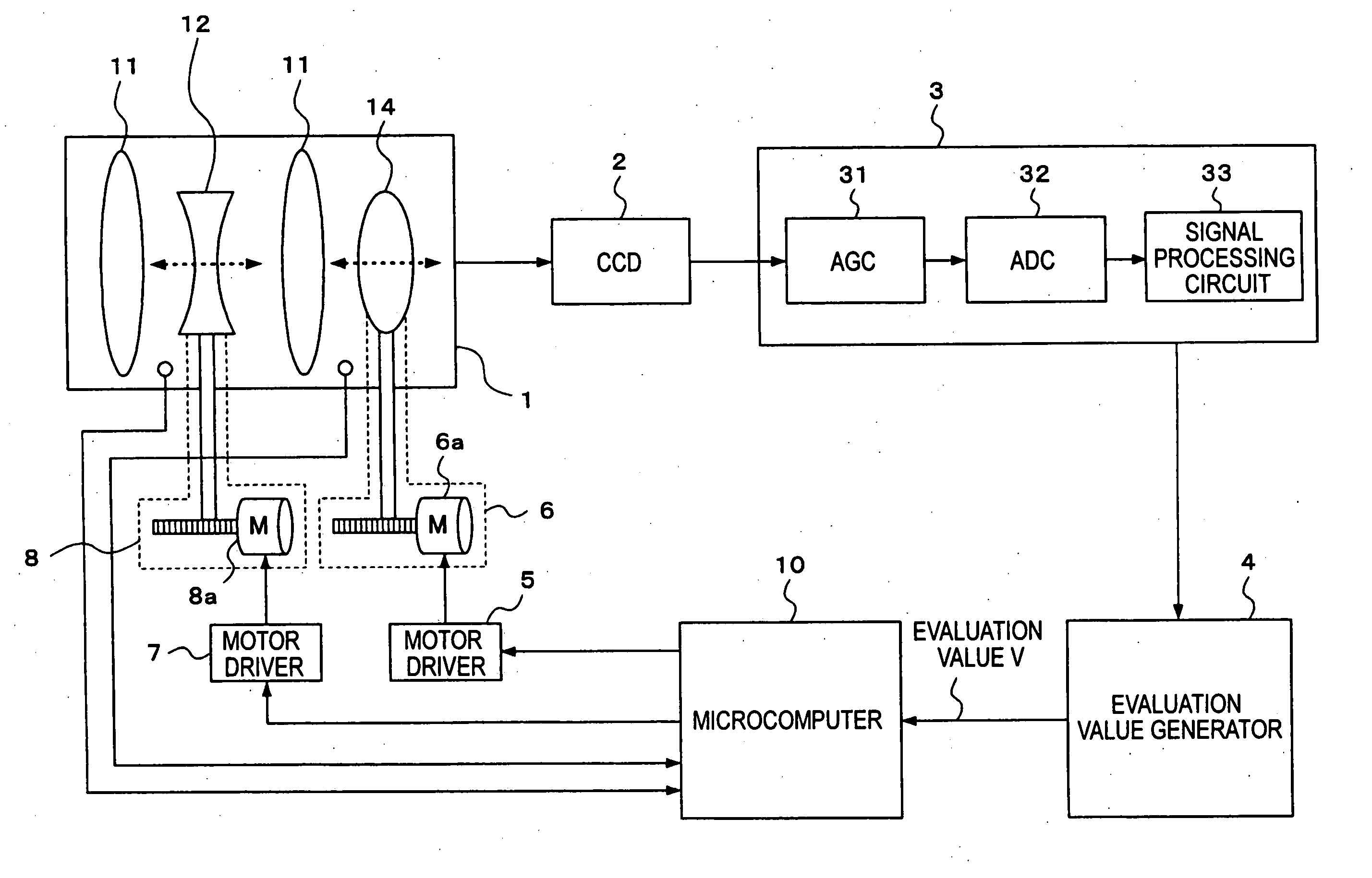
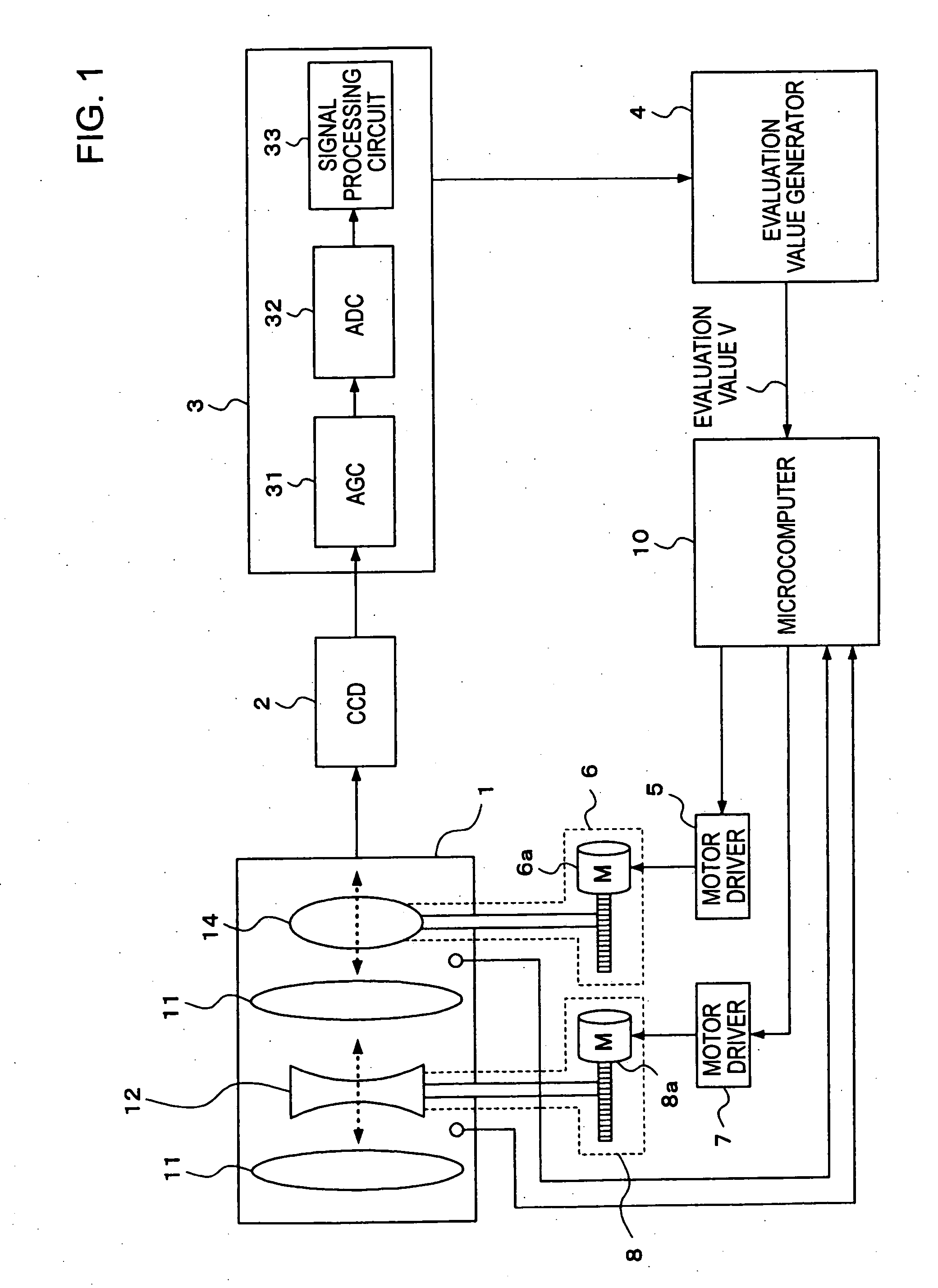
[0021]FIG. 1 shows the structure of a main portion of a video camera apparatus according to an embodiment of the present invention. For example, the video camera apparatus is installed in a predetermined position to perform photographing in a monitoring camera system.

[0022] Referring to FIG. 1, in the video camera apparatus, a lens block 1 includes, for example, a predetermined number of image pickup lenses. The lens block 1 forms an image on a light-receiving surface of a charge-coupled device (CCD) 2 using incident light as image pickup light. In this example, a fixed lens 11, a zoom lens 12, a fixed lens 13, and a focus lens 14 are shown as lenses forming the lens block 1. However, FIG. 1 simply illustrates that lenses including at least a fixed lens, a zoom lens, and a focus lens form a lens system of the lens block 1. The lens arrangement forming the lens system can be changed in an appropriate fashion.

[0023] The focus lens 14 is provided so as to be movable along an optical ...


PUM


Abstract

A focus control device includes a lens unit including a focus lens; a focus lens driving mechanism that moves the focus lens to achieve an in-focus state; a focus status detector that detects a focus status acquired by the focus lens; a drive control unit that controls the focus lens driving mechanism so that the detected focus status is the in-focus state; a change detector that detects that an evaluation value for focus control has changed by a threshold value or more; and an execution control unit that waits in a state in which the drive control unit does not control the focus lens driving mechanism for a waiting time starting from a time when the change detector detects that the evaluation value has changed by the predetermined threshold value or more, and that causes the drive control unit to control the focus lens driving mechanism when the state in which the evaluation value has changed by the predetermined threshold value or more is maintained until the waiting time has elapsed.

Description

CROSS-REFERENCE TO RELATED APPLICATIONS [0001] The present application claims priority from Japanese Patent Application No. JP 2005-021852 filed on Jan. 28, 2005, the disclosure of which is hereby incorporated by reference herein. BACKGROUND OF THE INVENTION [0002] The present invention relates to a focus control device that is provided in an image pickup apparatus, such as a video camera, and that controls a focus status of an image acquired by a lens portion and to a focus control method for the focus control device. [0003] Nowadays, most of image pickup apparatuses, such as portable consumer video cameras and still cameras, have an automatic focus function. As a method for such automatic focus control, a contrast method using contrast information of an image signal acquired from image pickup light by a lens portion is widely known. In addition, as the contrast method, a hill-climbing method is described, for example, in Japanese Patent No. 2966458. [0004] For example, such an aut...

Claims


Application Information

Patent Timeline
Patent Type & Authority Applications(United States)
IPC IPC(8): G03B13/00
CPCH04N5/23212H04N23/673H04N23/67
Inventor KOBAYASHI, FUMIKAZU
Owner SONY CORP
Why Eureka
Try Eureka