Image matching method and image interpolation method using the same

Inactive Publication Date: 2006-08-31
KK TOSHIBA
View PDF13 Cites 50 Cited by
  • Summary
  • Abstract
  • Description
  • Claims
  • Application Information

AI Technical Summary

Benefits of technology

[0041]FIG. 29 is a diagram for explaining that the detection o

Problems solved by technology

However, there is a problem that constraint condition to make the mapping smooth acts on a discontinuous part of motion, resulting in that the discontinuous mapping cannot be expr

Method used


Image

  • Image matching method and image interpolation method using the same
  • Image matching method and image interpolation method using the same
  • Image matching method and image interpolation method using the same

Examples


first embodiment

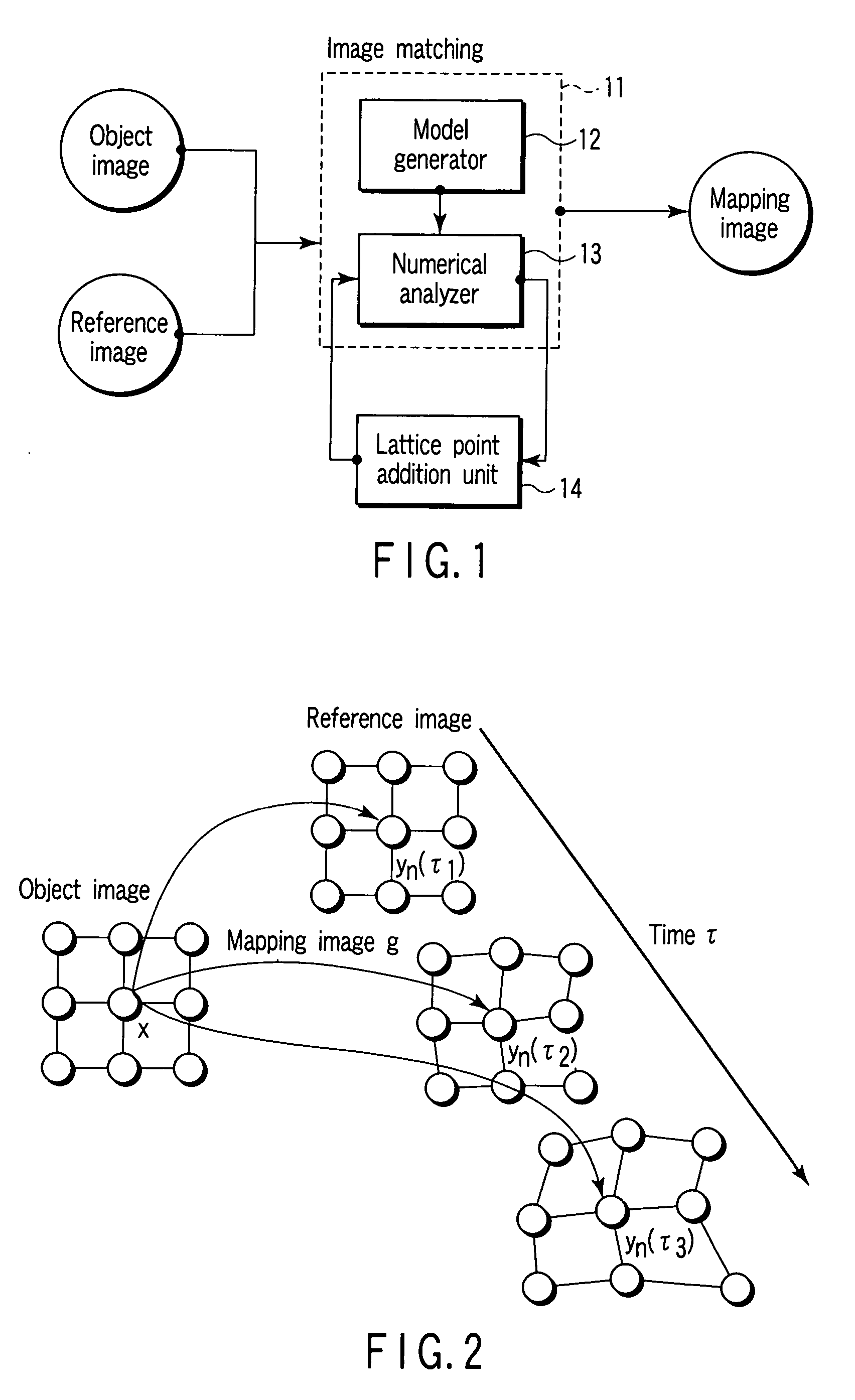
[0055] There will be described the present embodiment according to a block diagram of FIG. 1.

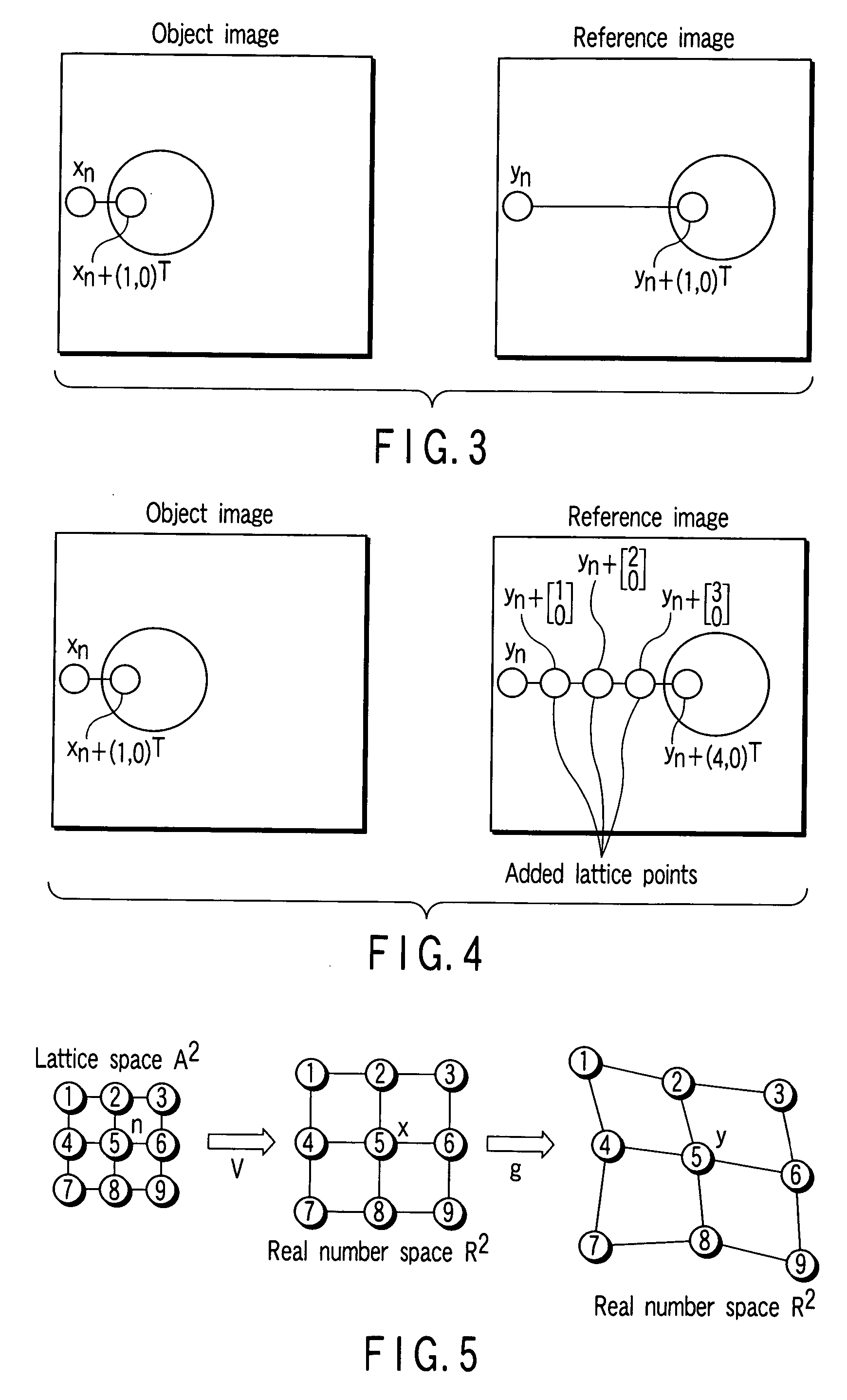
[0056] According to FIG. 1, an image matching unit 11 comprising a processor including a memory and so on comprises a model creation module 12 and a numerical analysis module 13. When a source image and a reference image are input to the image matching unit 11, the same parts of the object and reference images stored in a frame memory, for example, the same parts of 3D image are matched. In other words, when two images of the object and reference images are input, a dynamic model is created using dynamic concept. Because this dynamic model is output from the model creation module 12 in form of an ordinary differential equation, the numerical analysis module 13 solves the output repeatedly by a general numerical solution. The image of the result provided in the last of repeated computation becomes a final state of matching. In the present embodiment, a lattice point addition module 14 compri...

second embodiment

[0122] (Single Direction Occlusion Model)

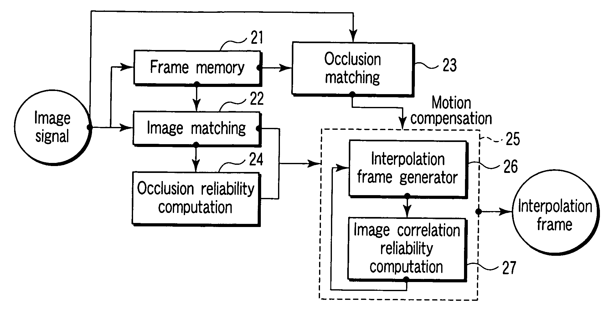
[0123] The present embodiment is explained according to the block diagram of FIG. 13 and the flow chart FIG. 14. The present embodiment considers a problem how an interpolation is done for the purpose of making an occlusion region correspond to a motion image well, and is directed to generating an interpolation frame containing an occlusion area between frames of an image based on an image signal of a motion image.

[0124] When an interpolation frame is generated, there is an occlusion problem making it difficult to generate an interpolation frame of high quality. The present embodiment provides a method for generating an interpolation frame of high quality by interpolating an occlusion region adequately.

[0125] Schematically, this method performs an ordinal image matching (surface matching) in a time interval t1-t2, and an occlusion matching in a time interval t2-t3. A reliability of an occlusion region is obtained from a result of the ordin...

third embodiment

[0175] (Bidirectional Occlusion Model)

[0176] The present embodiment is explained according to the block diagram of FIG. 22 and the flow chart of FIG. 23. The present embodiment is directed to generating an interpolation frame between the frames of an image signal of a motion image.

[0177] When the interpolation frame is generated, it is difficult owing to occlusion problem to generate an interpolation frame of high quality. The second embodiment provides a method dealing with uncovered occlusion. The present embodiment can deal with covered occlusion as well as uncovered occlusion, by matching in bi-direction of forward and backward with respect to a time axis.

[0178] The image signal of the motion image is divided into frames, and subjected to processing. In this time, each frame is stored in a frame memory 31, and some frames can be accessed at the same time. A frame in the time t is referred to as a reference frame t, a frame in the time t+lΔt is referred to as a reference frame...


PUM


Abstract

An image matching method includes setting first and second lattices to first and second images respectively, computing potential force to each second lattice point of the second lattice by a gradient of an image correlation potential energy based on a position of each first lattice point and pixel thereof and a position of the second lattice point and pixel thereof, computing elasticity force to the second lattice point from elasticity energy between the second and adjacent lattice points, computing frictional force occurring at the second lattice point, performing a numerical analysis of an equation of motion regarding the second lattice point and based on the potential force, elasticity force and frictional force to obtain a convergence state of the second lattice points, and adding a new lattice point between an adjacent lattice point pair of second lattice points according to a distance between the adjacent lattice point pair.

Description

CROSS-REFERENCE TO RELATED APPLICATIONS [0001] This application is based upon and claims the benefit of priority from prior Japanese Patent Applications No. 2005-039623, filed Feb. 16, 2005; and No. 2005-336291, filed Nov. 21, 2005, the entire contents of both of which are incorporated herein by reference. BACKGROUND OF THE INVENTION [0002] 1. Field of the Invention [0003] The present invention relates to an image matching method for matching images by detecting corresponding points from two images, and an image interpolation method for interpolating the image using the same. [0004] 2. Description of the Related Art [0005] A technique of image matching to obtain association between one image and the other image is a basic technique in many technical fields such as motion detection, stereo matching, image morphing, image recognition, and video encoding. [0006] According to Murat Tekalp, “Digital Video Processing”, Prentice Hall, 1995, a technique of image matching can be sorted to fo...

Claims


Application Information

Patent Timeline
IPC IPC(8): G06K9/32G06K9/36
CPCG06K9/6206G06T3/0093G06T7/0026G06T7/32G06V10/754
Inventor MISHIMA, NAOITOH, GOHBABA, MASAHIRO
Owner KK TOSHIBA
Why Eureka
Try Eureka