

Method and assembly for maintaining structural stability and configuration of golf course sand bunker borders
- Summary
- Abstract
- Description
- Claims
- Application Information
AI Technical Summary
Benefits of technology
Problems solved by technology
Method used
Image

Examples
Embodiment Construction
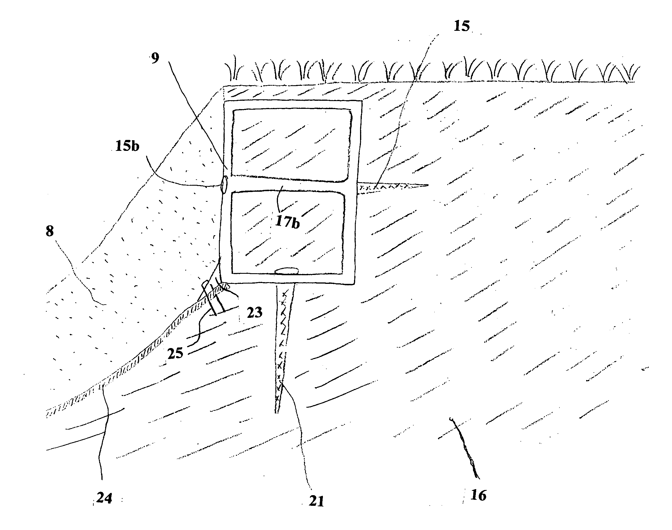
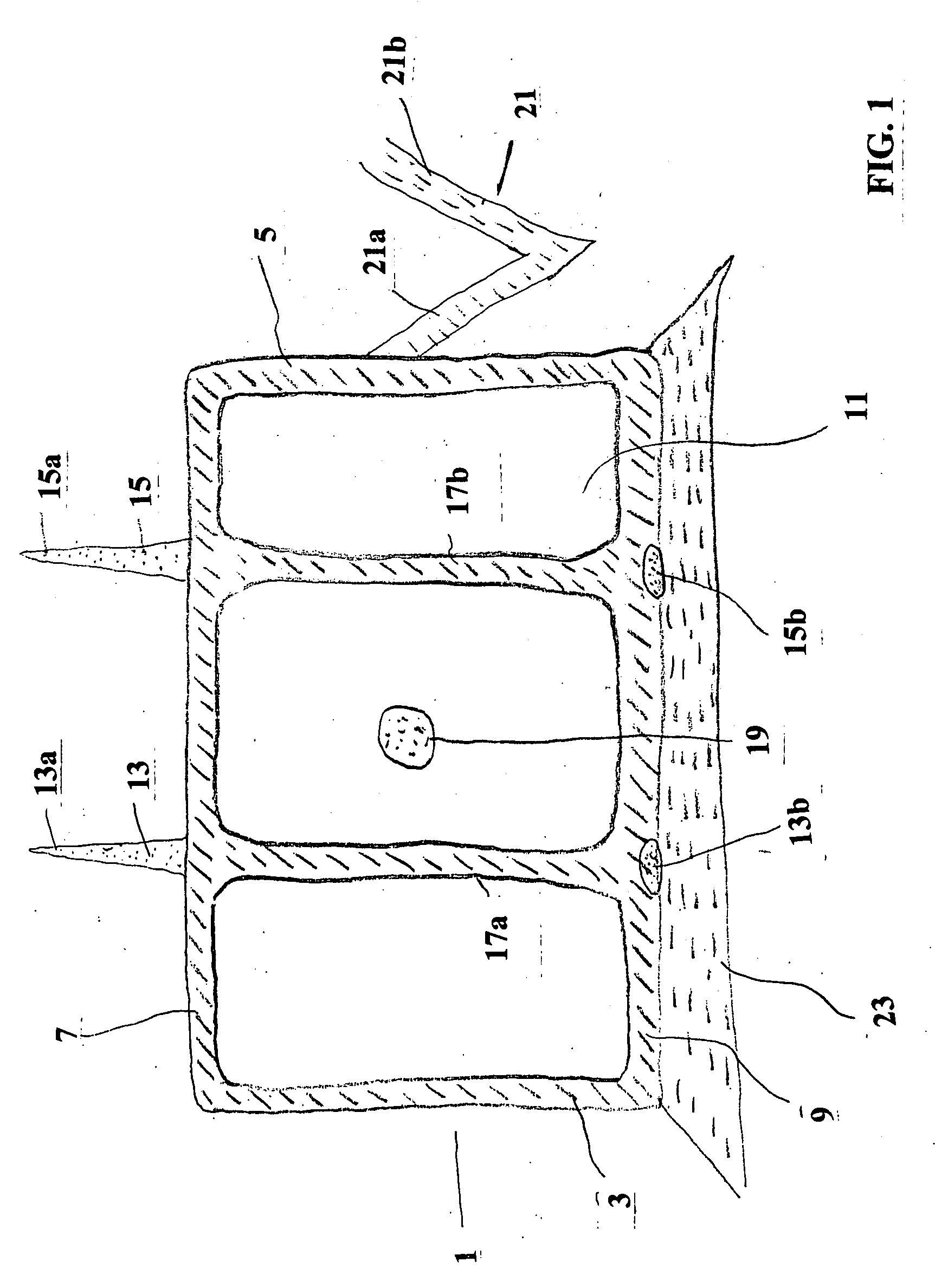
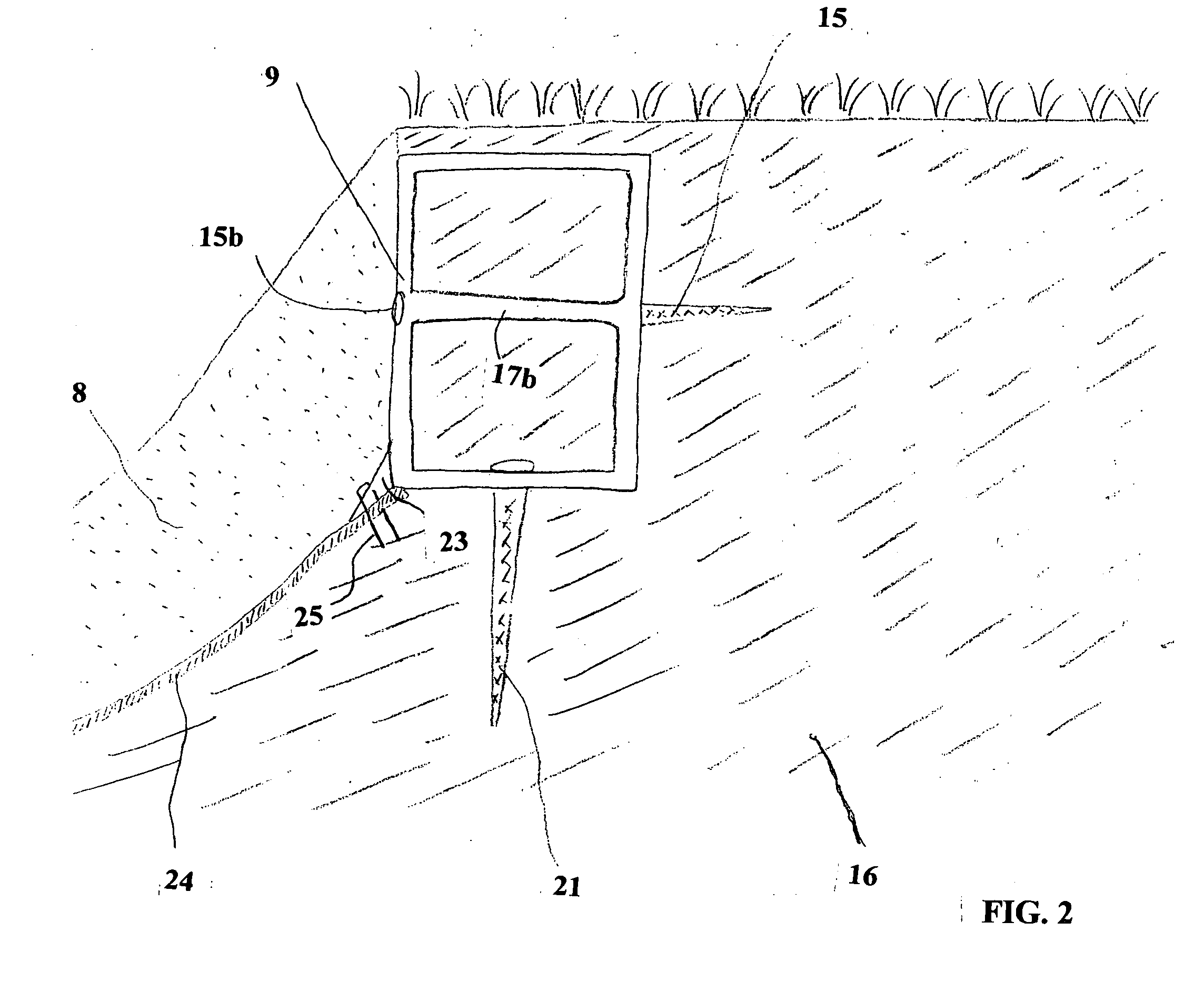
[0025] The compartment illustrated in FIGS. 1 and 2 are generally designated as 1 and comprises two generally parallel side panels 3 and 5, a front panel 7, a generally parallel rear panel 9 and a bottom closure panel 11. Compartment 1 is open at its top and is provided with two spaced apart generally parallel spikes 13,15 each of which protrude through the front panel 7 and the rear panel 9 a pre-desired distance into the soil area 16 as shown in FIG. 2 and will hereinafter be described in more detail. The front ends 13a,15a of each spike 13,15 is sharpened in a projectile-like manner for ease of insertion and securement into soil around sand bunker area 18 and each spike terminates at its rear end with an enlarged spike head such as 13b,15b each of which abuts against the rear panel 9 when each spike is inserted through the soil to its fullest length. Within the compartment 1 each spike is disposed within its respective sleeve 17a,17b and is adapted to be rotably advanced into and...
PUM
 Abstract
Description
Claims
Application Information