Eureka AIR delivers breakthrough ideas for toughest innovation challenges, trusted by R&D personnel around the world.

Stitching system hold-down

Active Publication Date: 2006-02-02
SIMPSON STRONG TIE
View PDF55 Cites 4 Cited by
  • Summary
  • Abstract
  • Description
  • Claims
  • Application Information

AI Technical Summary

Benefits of technology

[0096] Two alternative side wall patterns are illustrated in FIGS. 11B/11E and 11D. A first alternative of the sidewall pattern is illustrated in FIG. 11B. In FIG. 11B, sidewall 1168 includes a ridge 1104, and sidewall 1162 a ridge 1110 running the length of each sidewall. Ridges 1108 and 1110 provide additional rigidity along the length (L) of the hold-down 110. FIG. 11D, illustrates an alternative hold-down 1100-1 in which each wall 1162, 1168 has ends flared outwardly, away from channel 1102 of the hold-down.
[0097] The hold-down shown in FIGS. 11A-11F has an advantage of being folded into form from a single pi

Problems solved by technology

High winds and earthquakes, in particular, cause forces that place considerable strain on the stability of a building.
For example, bolt slip can occur at hold-down stud bolts.
When a hold-down is installed on only one side of the stud, an eccentricity exists during loading which can cause more movement in the wall system.
Wood at the end of the studs (sill plates, rim joists, etc.) may crush under normal dead and live loading; additional compressive forces due to overturning during earthquake and high wind loads add to the deflection.

Method used


Image

  • Stitching system hold-down
  • Stitching system hold-down
  • Stitching system hold-down

Examples


Embodiment Construction

[0059] The invention provides a unique apparatus for ensuring stability in a building by re-enforcing the attachment of an elongated wood column to a body, such as a building support to a building foundation. Various embodiments of the coupling system, provided in an exemplary embodiment of a hold-down, are included herein.

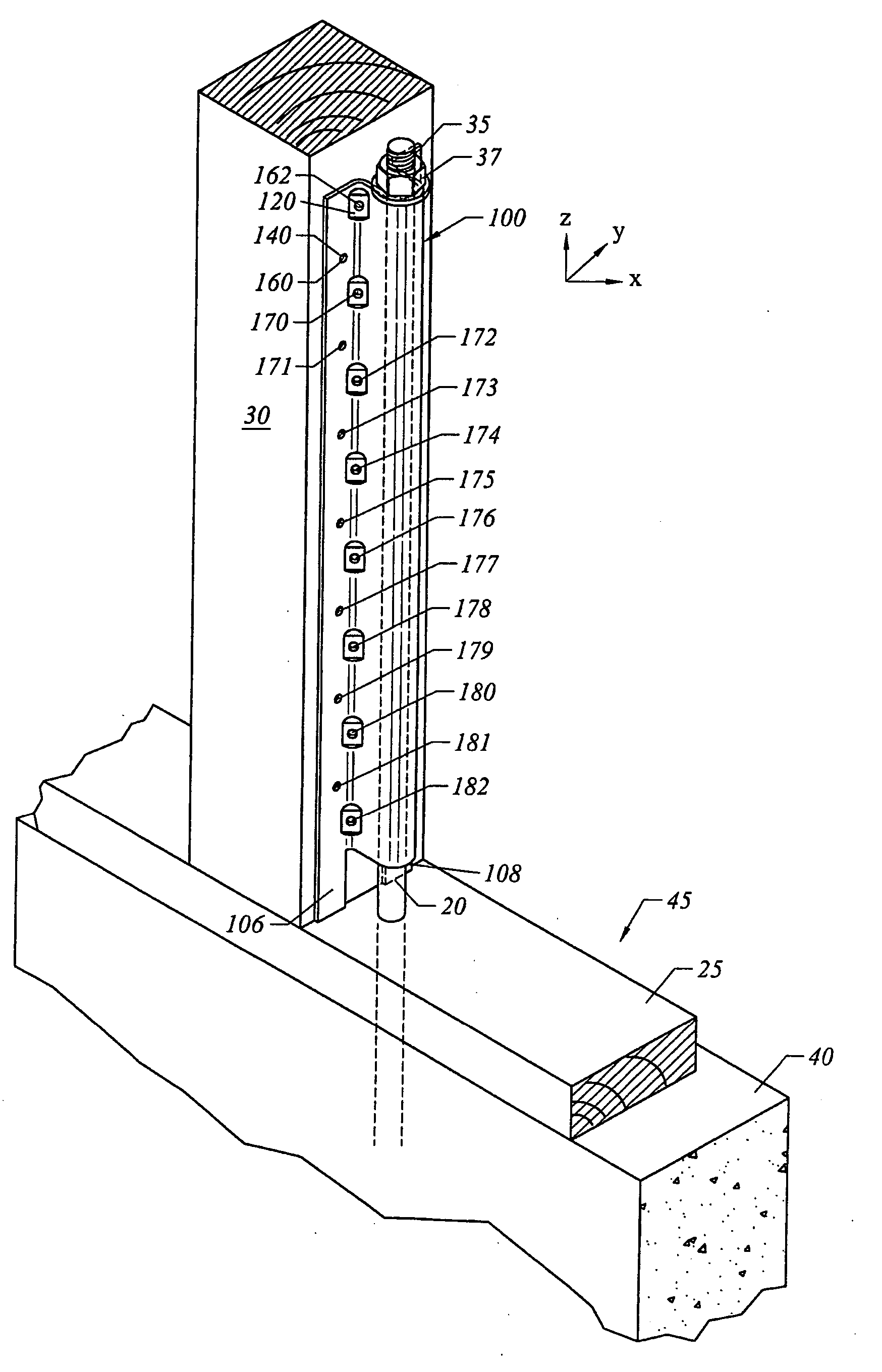
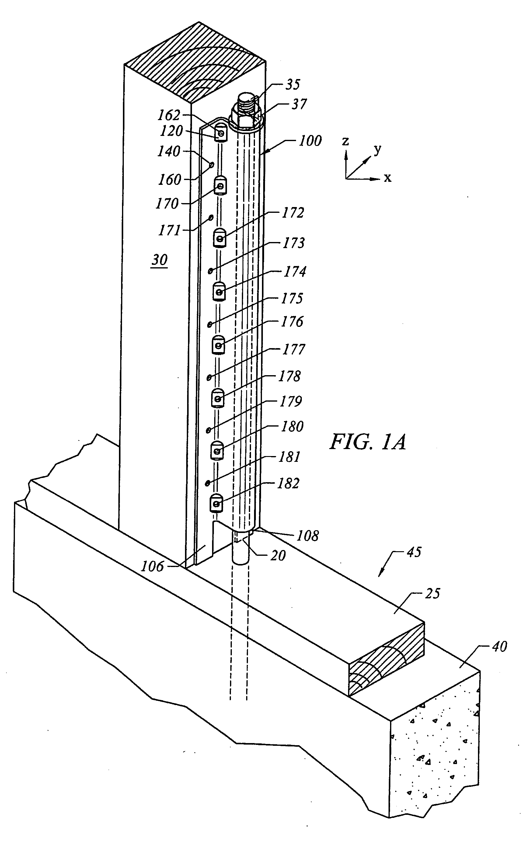
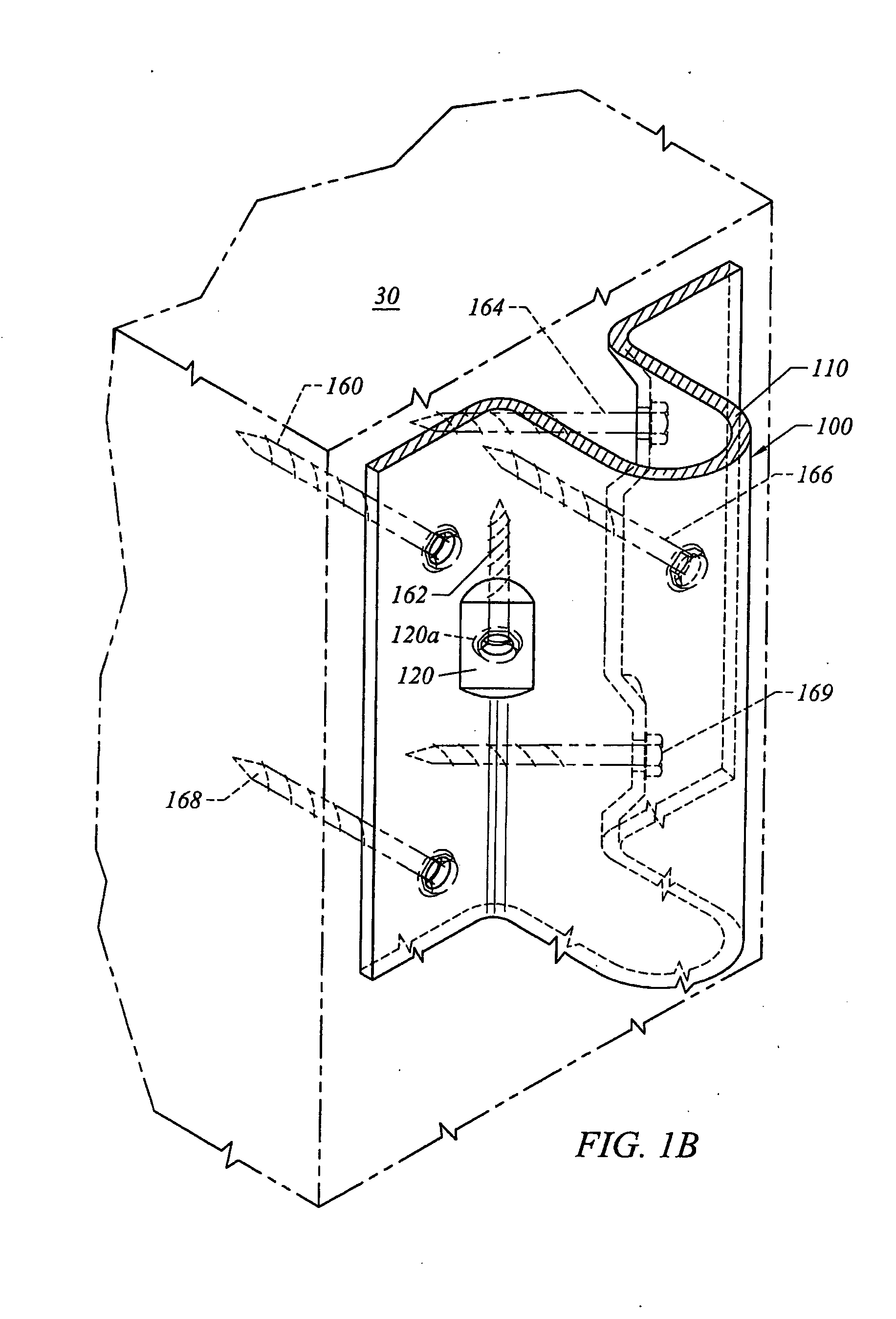
[0060]FIG. 1A is a perspective view and FIG. 1B an enlarged, partial perspective view of a hold-down 100 created in accordance with the present invention. As shown in FIG. 1A, hold-down 100 secures one end of an anchor bolt 20, which has a second end secured in the foundation 45 of a building. In FIG. 1A, the foundation includes a concrete section 40 and mud sill 25. The particular construction and placement of the anchor bolt 20 in the foundation installation 45 is not critical to the hold-down apparatus of the invention.

[0061] As shown in FIGS. 1A and 1B, the hold-down 100 is secured to a building column 30 by a plurality of dowel fasteners 160, 162, 164, 166....


PUM


Abstract

A coupling system for securing an elongated wood member having a surface to a second body comprises a stitching body having a first end and a second end defining a length, and a first side and a second side. A first plurality of angled fastener bores is positioned generally on the first side of the stitching body, each configured to position a first side fastener element resting therein at least a first angle with respect to the surface of the elongated wood member. A second plurality of angled fastener bores positioned generally on the second side of the stitching body, each configured to position a second side fastener element resting therein at least a second angle with respect to the surface of the elongated wood member, such that ones of said second side fasteners and said first side fasteners form an intersection when viewed along the length of the stitching body. In one aspect, the coupling system is a hold-down securing a column having a surface to a foundation. The hold-down includes an anchor securing section securing an anchor bolt having a first end positioned in a foundation, the securing section having a first side and a second side defining a width, and a first end and a second end defining a length. A method for installing a hold-down is also provided.

Description

CLAIM OF PRIORITY [0001] This application claims the benefit of U.S. patent application Ser. No. 10 / 693,256, “Stitching System Hold-Down,” filed on Oct. 24, 2003, by William F. Leek, which is incorporated herein by reference.BACKGROUND OF THE INVENTION [0002] 1. Field of the Invention [0003] The present invention is directed to an improved construction device, and specifically an improved hold-down device for building construction applications. [0004] 2. Description of the Related Art [0005] Nature's elements exert extreme forces on building walls and elements. High winds and earthquakes, in particular, cause forces that place considerable strain on the stability of a building. Proper distribution of these forces is critical to ensure the stability of a structure. At the core of building stability is the building's foundation and thus securing the walls of a building to the foundation greatly improves structural performance. [0006] Structures known as “hold-downs” are used to transf...

Claims


Application Information

Patent Timeline
IPC IPC(8): E02D27/00
CPCE02D27/34Y10T403/3973E04H9/14E04B2001/2684Y10T403/46Y02A50/00
Inventor LEEK, WILLIAM F.KHACHADOURIAN, ARAMLIN, JIN JIE
Owner SIMPSON STRONG TIE
Why Eureka
Eureka Blog
Learn More