
Protection profile for a substantially plate-shaped body

a protection profile and substantially plate-shaped technology, applied in the direction of packaging goods, plastic containers, transportation and packaging, etc., can solve the problems of insufficient protection of the peripheral regions of the plate-shaped body, insufficient for many applications, and insufficiently large, etc., to achieve excellent shock absorption and widen the effect of the area

Inactive Publication Date: 2006-09-07
ARMACELL ENTERPRISE GMBH
View PDF2 Cites 7 Cited by
  • Summary
  • Abstract
  • Description
  • Claims
  • Application Information

AI Technical Summary

Benefits of technology

[0008] The object of the invention consists in configuring the protection profile of the kind initially specified so that, apart from the excellent shock-absorption for the plate-shaped body in the protection profile also dependent on loading, the friction between the protection profile and the peripheral region of the inserted plate-shaped body can be increased and the supporting force can be distributed over a wider area.
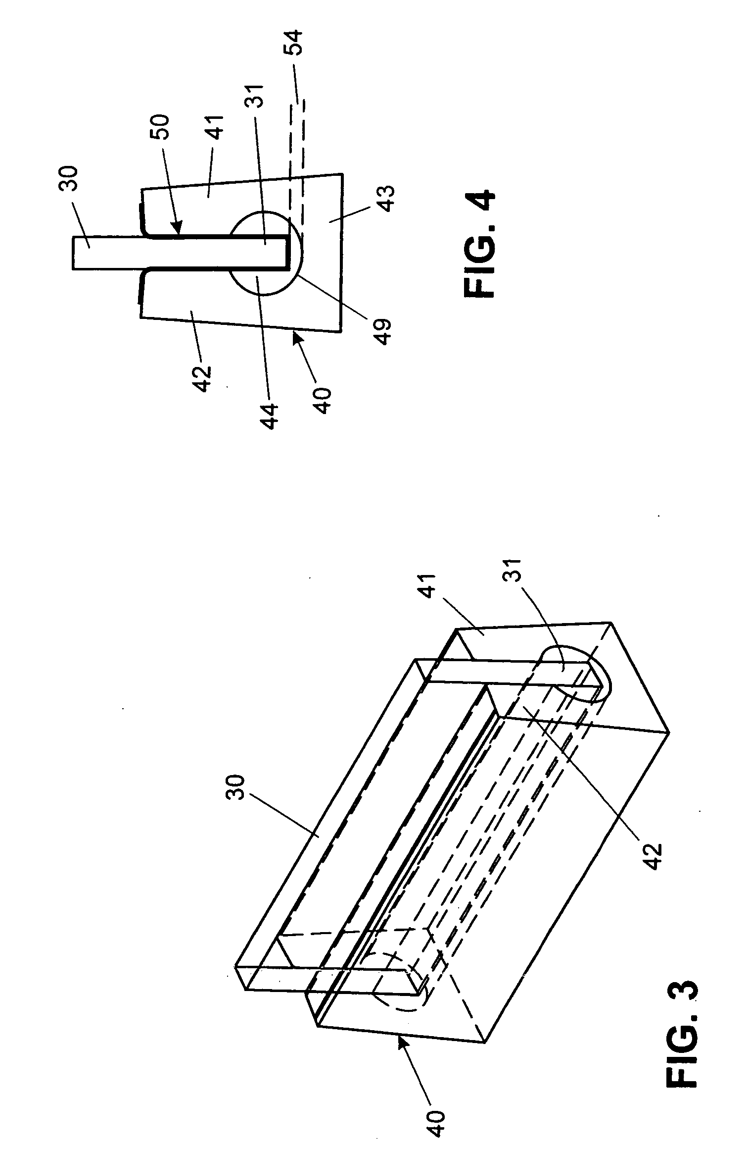
[0010] In this embodiment of the protection profile the foil inlay, when the plate-shaped body is being inserted in its inner space, ensures good shock-absorption during insertion and whenever impacts occur during transport. This excellent shock-absorption is due both to the plastic and flexible expansion of the foil inlay as well as the foam at the junction points with the foil inlay, without at the same time the base wall of the foil inlay coming into contact with the slat inner face, thus a certain resilience is possible within this part of the air-filled receiving space of the profile strip. The plate-shaped body lying on the base wall of the foil inlay exerts pressure thereon, which propagates in the foil inlay and because the foil inlay is joined to the exposed front faces of the profile strip, leads to a moment of force, which moves the flanks of the profile strip with the foil inlay towards one another, as a result of which the retaining pressure on the plate-shaped body is increased and thus the plate-shaped body is securely held in the protection profile and increased carrying load is achieved at the same time.
[0013] Foam and foil expediently consist of the same product group, making unadulterated re-cycling possible. If special demands related to protection, shock-absorption, cut-resistance, adhesion, load-distribution etc. are imposed on the protection profile, a foil inlay in the form of a multi-ply foil can be used, whereby the individual layers of the foil, in particular the external layers, can have varying properties and consist of different materials. For example the layer coming into contact with the plate-shaped body can have very good adhesion capacity, while that of the layer facing the profile strip can be easy to weld or bond therewith. For stabilization an intermediate layer, made of polyethylene terephthalate for example, may also be provided.
[0018] In order to increase the shock-absorption on the part of the foil inlay when the plate-shaped body is being inserted in the protection profile, holes or cutouts may be provided in the foil inlay. The foil inlay can also be formed with a mesh structure. To ensure sufficient adhesion of the foil inlay to the profile strip a longitudinal fold opening in the direction of the slat inner face can be provided with concealed integrated glue or adhesive on the sidewalls of the foil inlay. Thus simple application of the protection profile with easy sliding and exclusive adhesion should be possible.
[0019] It has also shown to be practical if the receiving space is expanded on the slat side, which can be simply achieved by extrusion and which results in greater flexibility, creates space for sensitive sealing rims and reduces the notch effect whenever the slats of the profile strip are obtained by cutting.

Problems solved by technology

It has been shown that the protection of the peripheral regions of the plate-shaped body, achievable with the known profile, is insufficient for many applications.
The retention of the peripheral region of the plate-shaped body in the receiving space is alone determined by the precision of fit between plate thickness and distance apart of the profile flanks as well as by the friction coefficient of the foam and is therefore not always adequate.

Method used


Image

  • Protection profile for a substantially plate-shaped body
  • Protection profile for a substantially plate-shaped body
  • Protection profile for a substantially plate-shaped body

Examples


Embodiment Construction

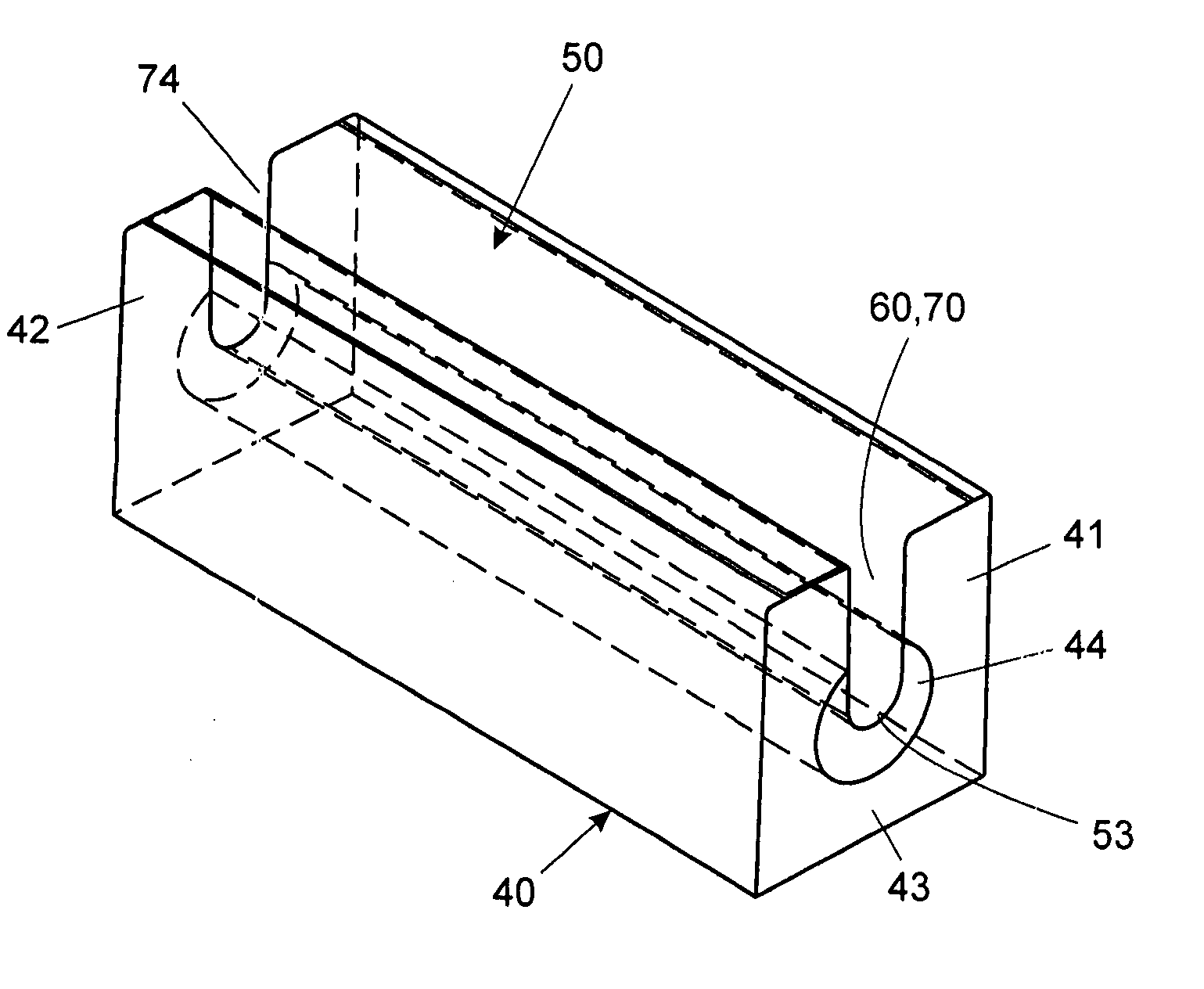
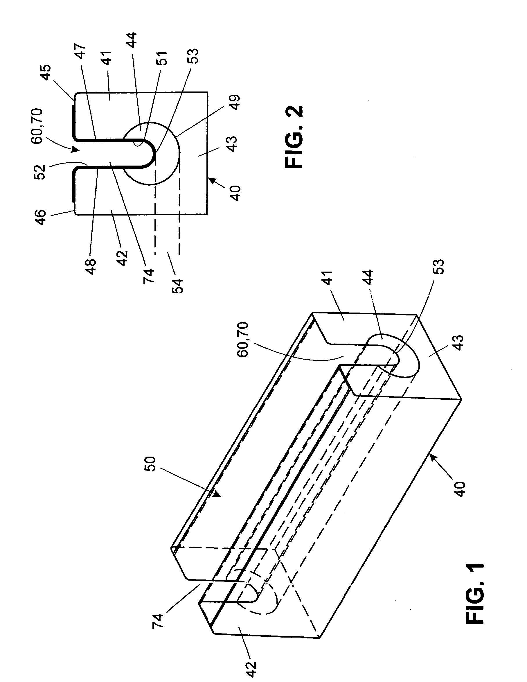
[0042] The protection profile shown in FIGS. 1 to 4 has a U-profile strip 40 made of a thermoplastic foam. The U-profile strip 40 has two flanks 41 and 42 as well as a slat 43, which form one piece. On the side facing the slat 43 each flank 41 and 42 in each case has an exposed front face 45 and 46. The flank 41 has a flank inner face 47, the flank 42 a flank inner face 48. The slat 43 has a slat inner face 49. The flank inner faces 47 and 48 changing into the slat inner face 49 delimit a receiving space 44, which has a strip opening 60 extending in the longitudinal direction of the U-profile strip 40 between the exposed front faces45 and 46 of the flanks 41 and 42.

[0043] A U-shaped foil inlay 50, whose strength, in particular tensile strength, but also cutting resistance, slip resistance and the like is greater than that of the foam or which possesses other properties, is arranged in the receiving space 44 for contact with the plate-shaped body 30. The foil inlay 50 has sidewalls ...


PUM


Abstract

The protection profile for a substantially plate-shaped body (30) includes a profile strip (40) made of thermoplastic foam with two flanks (41, 42) and a slat (43). In the receiving space (44) of the profile strip (40) a foil inlay (50) is inserted in such a way that the exposed ends of its sidewalls (51, 52) are firmly joined to the exposed front faces (45, 46) of the flanks (41, 42) and its base wall (53) is arranged at such a distance (54) from the slat (43) that, also with the plate-shaped body (30) inserted in the foil inlay (50), the base wall (53) does not come into contact with the slat (43), but under the weight of the plate-shaped body (30) the foil inlay (50) presses the flanks (41, 42) of the profile strip against the plate-shaped body (30).

Description

BACKGROUND OF THE INVENTION [0001] 1. Field of the Invention [0002] The invention relates to a protection profile for a substantially plate-shaped body. The protection profile has a profile strip made of foamed plastic, which comprises two flanks in each case with a flank inner face and an exposed front face as well as a slat connecting the flanks with a slat inner face. The flank inner faces and the slat inner face delimit a receiving space, which between the exposed front faces of the flanks has a strip opening extending in the longitudinal direction of the profile strip. An inlay is provided in the receiving space for contact with the plate-shaped body, which is joined on the profile side and has a strength greater than that of the foam. [0003] 2. Description of the Background [0004] German Patent DE 36 26 765 C2 discloses a packing body comprising a base plate made of cardboard, on which a carrier layer made of polymerized polyethylene foam with a thickness of approximately 10 m...

Claims


Application Information

Patent Timeline
IPC IPC(8): E04D1/36
CPCB65D81/053B65D85/48B65D81/055B65D2581/055
Inventor KARL, REINHARD
Owner ARMACELL ENTERPRISE GMBH
Learn More