
Respiratory mask having gas washout vent & gas washout vent assembly for a respiratory mask

a technology of respiratory mask and vent, which is applied in the direction of breathing mask, breathing protection, other medical devices, etc., can solve the problem of noise generated by exhausting the atmosphere of exhaled gas through the ven

Inactive Publication Date: 2006-09-07
RESMED LTD
View PDF99 Cites 33 Cited by
  • Summary
  • Abstract
  • Description
  • Claims
  • Application Information

AI Technical Summary

Benefits of technology

The present invention provides a vent assembly for a mask used in CPAP treatment. The vent assembly is a thin air permeable membrane that can be attached to a mask. The membrane is thinner than the mask frame and is made of a hydrophobic material such as PTFE or stainless steel. The membrane has a reference pore size of 10 to 15 microns and can be constructed from expanded PTFE or stainless steel. The vent assembly can be attached to a mask or a separate gas washout vent. The invention also provides a respiratory mask arrangement with the vent assembly and an apparatus for delivering CPAP with the mask arrangement. The technical effects of the invention include improved breathability, reduced noise, and improved comfort for patients during CPAP treatment.

Problems solved by technology

The exhausting to atmosphere of exhaled gas through the vent creates noise.

Method used


Image

  • Respiratory mask having gas washout vent & gas washout vent assembly for a respiratory mask
  • Respiratory mask having gas washout vent & gas washout vent assembly for a respiratory mask
  • Respiratory mask having gas washout vent & gas washout vent assembly for a respiratory mask

Examples


first embodiment

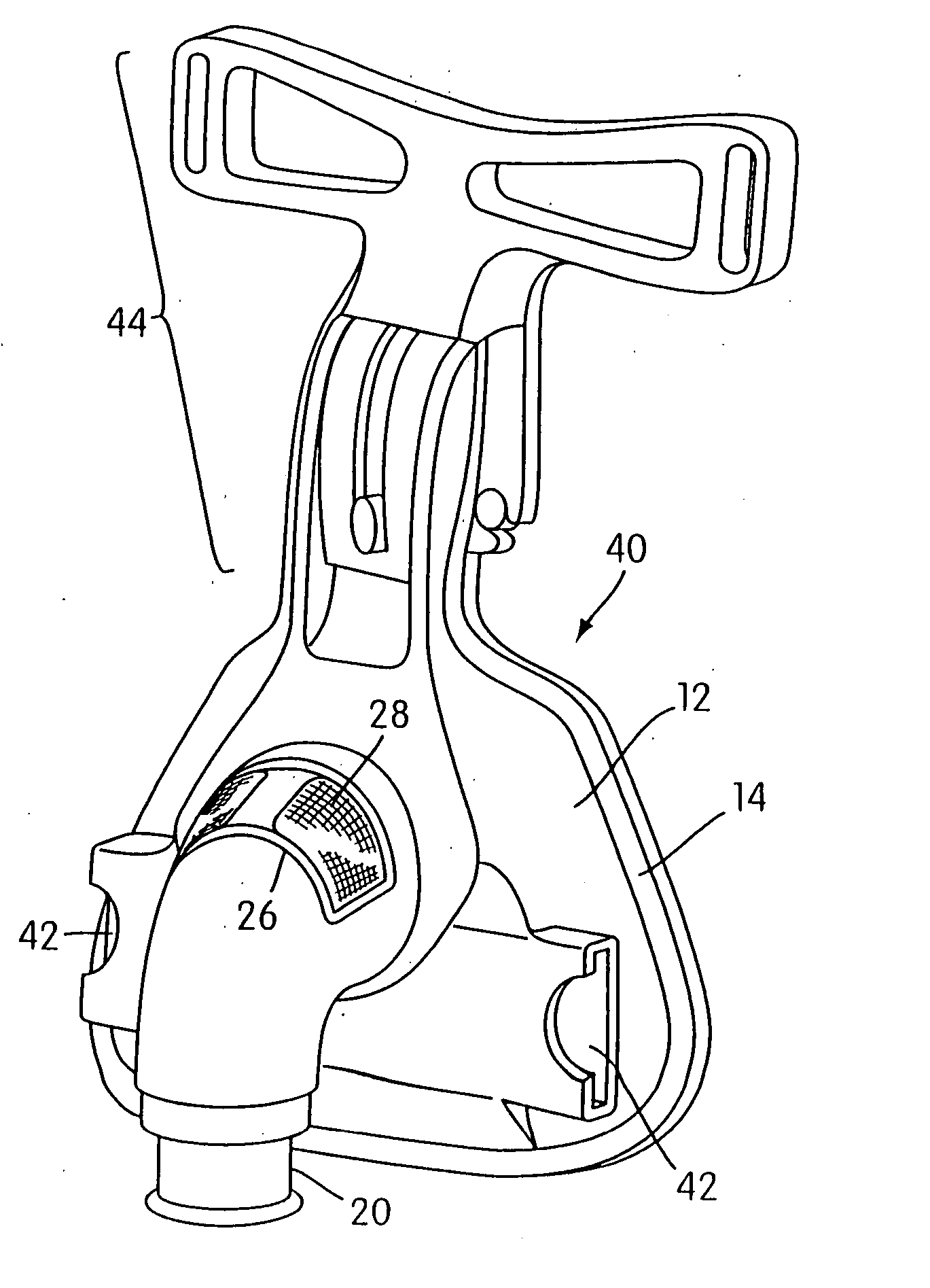
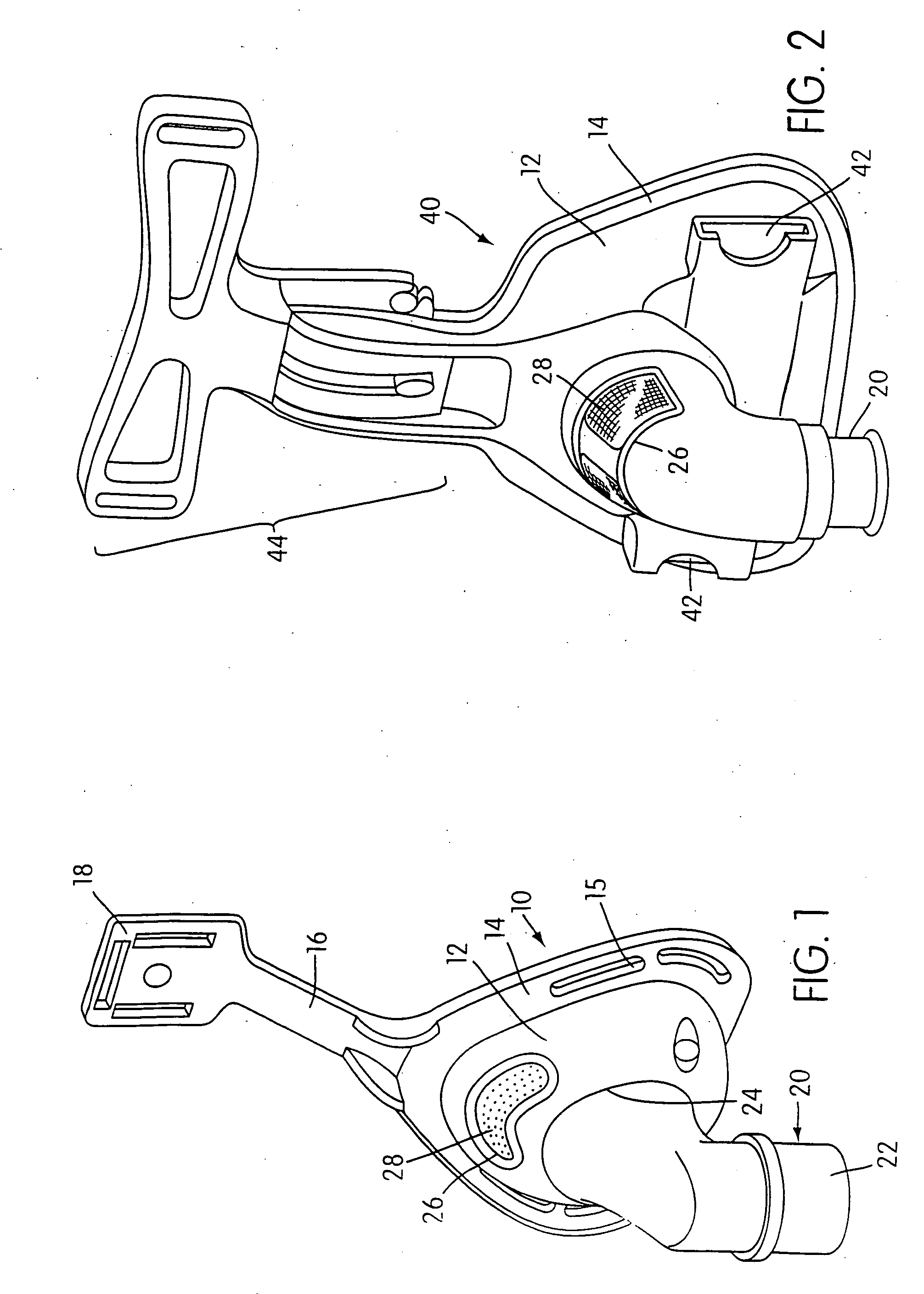
[0044]FIG. 1 shows a nasal respiratory mask 10 according to the invention. The mask 10 includes a rigid plastic mask shell 12, which has a peripheral flange 14 for mounting of a cushion (not shown) to the shell 12. The cushion abuts the wearer's face in use and is well known in the art. The flange 14 includes slots 15 for the connection of mask restraining straps (not shown) that extend around the head of the wearer to maintain the mask 10 adjacent to the wearer's face. The straps are also known in the art. The shell 12 also includes an arm 16, which terminates in a fitting 18 that is adapted to connect to a forehead support (not shown), which is also known in the art.

[0045] The mask shell 12 includes a breathable gas inlet 20 which is rotatably mounted to the shell 12. The inlet 20 has a first end 22 which is adapted for connection with a breathable gas supply conduit (not shown) and a second end 24 which is adapted to connect to, and communicate the supplied gas to the interior of...

seventh embodiment

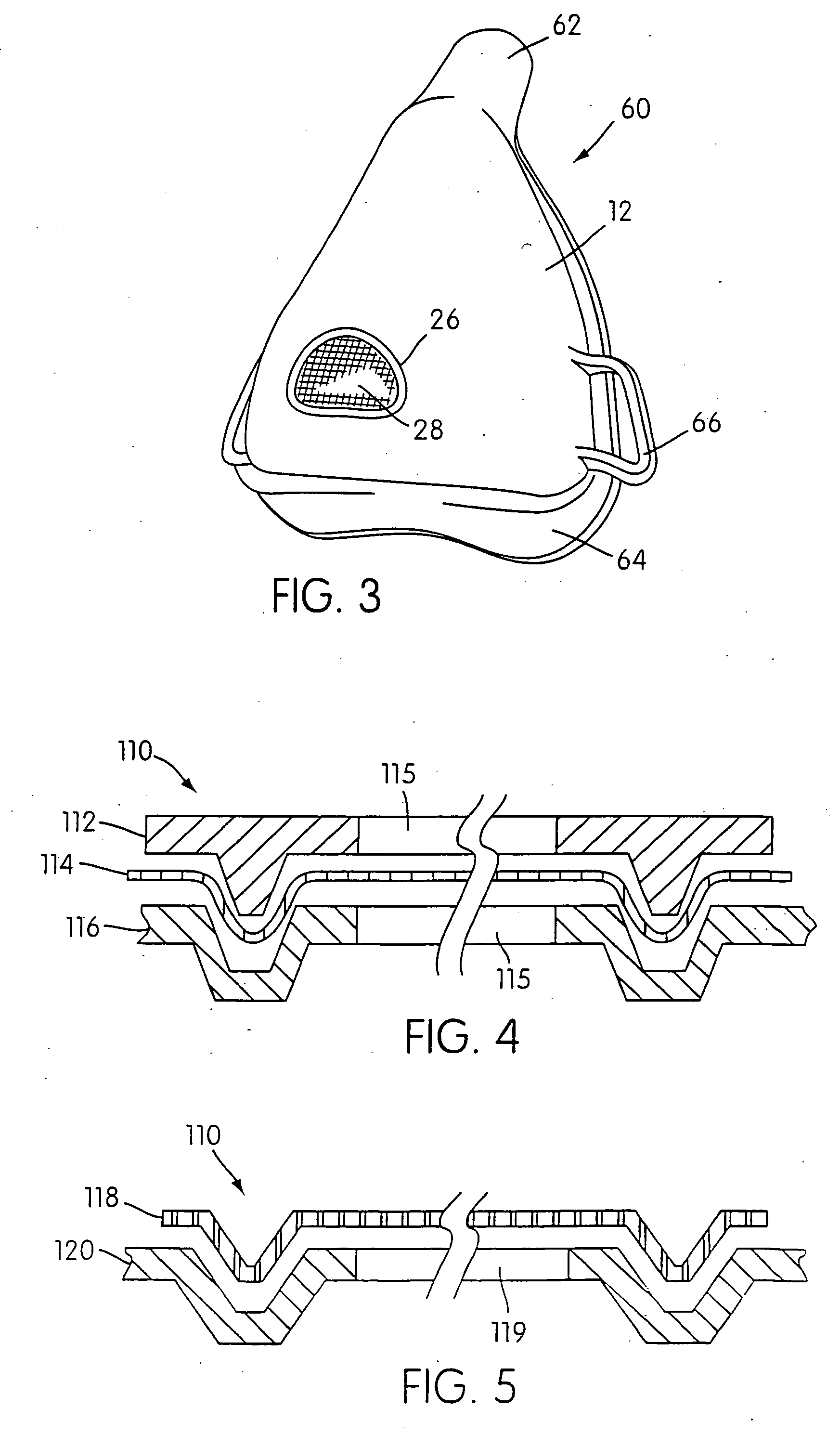
[0055]FIG. 7 shows a full-face respiratory mask 100 according to the invention. Once again like reference numerals to those used in denoting like features with previous embodiments have been used to denote like features in respect of this embodiment. The mask 100 is similar to the mask 80 shown in FIG. 6 in that the vent is provided in the inserts 82. However the mask 100 uses slotted extensions 66 to attach mask restraining straps (not shown), not openings 42.

[0056] As best seen in FIG. 8, which is a close-up view of the insert shown in FIG. 6, the insert 82 is comprises a cylindrical portion 86 sized to be a snug fit into a circular orifice 88 provided in the mask shell 12. The insert 82 located against the outer surface of the shell 12 by a peripheral flange 90. The inserts may be glued in position.

[0057]FIG. 9 shows a further embodiment of the invention in which an in-line vent assembly is provided. Like numerals are used to indicate like features with previous embodiments. In ...


PUM


Abstract

The present invention provides a vent assembly suitable for use with a respiratory mask of the type used in CPAP treatment. In one embodiment the vent is made of a thin air permeable membrane. Generally, the membrane is thinner than 0.5 mm. The membrane can be made of a hydrophobic material such as polytetrafluoroethylene (PTFE). The membrane can also be fabricated from expanded PTFE. The expanded PTFE membrane is mounted on a polypropylene scrim. The pores of the membrane have a reference pore size of 10 to 15 microns. In an alternative embodiment, the vent assembly includes a vent constructed from stainless steel. In another embodiment the membrane has a superficial cross-sectional area of approximately 500 mm2. In another embodiment the vent assembly comprises a membrane attached to a vent frame, the vent assembly forming an insert which can be removeably attached to a mask fame.

Description

BACKGROUND OF INVENTION [0001] 1. Field of the Invention [0002] The present invention relates to a respiratory mask and a vent for a respiratory mask. [0003] 2. General Background and Related Art [0004] The application of Continuous Positive Airway Pressure (CPAP) via a nasal mask is a common ameliorative treatment for sleep disordered breathing (SDB) including obstructive sleep apnea (OSA) as described in the applicant's U.S. Pat. No. 4,944,310. In CPAP treatment for OSA, air or other breathable gas is supplied to the entrance of a patient's airways at a pressure elevated above atmospheric pressure, typically in the range 3-20 cm H2O as measured in the patient interface. It is also known for the level of treatment pressure to vary during a period of treatment in accordance with patient need, that form of CPAP being known as automatically adjusting nasal CPAP treatment as described in the applicant's U.S. Pat. No. 5,245,995. [0005] Non-invasive positive pressure ventilation (NIPPV) ...

Claims


Application Information

Patent Timeline
Patent Type & Authority Applications(United States)
IPC IPC(8): A62B18/02A61M16/06A61M16/10
CPCA61M16/06A61M16/0683A62B18/02A61M16/0666A61M16/0633A61M16/1065A61M2202/0225A61M2205/42A61M16/0816A61M2205/7536A61M16/0825A61M16/0638A61M16/0644A61M16/065A61M2202/0085A61M16/22
Inventor DREW, JOANNEVIRR, ALEXANDERCRUMBLIN, GEOFFREY
Owner RESMED LTD
Learn More