Display and pixel circuit thereof

A technology of pixel circuits and displays, applied in static indicators, instruments, nonlinear optics, etc., can solve problems such as difference and color shift, and achieve the effect of improving color shift and increasing added value.

Inactive Publication Date: 2011-05-25
AU OPTRONICS CORP
View PDF6 Cites 12 Cited by
  • Summary
  • Abstract
  • Description
  • Claims
  • Application Information

AI Technical Summary

Problems solved by technology

In addition, when the color arrangement of the pixel electrod

Method used


Image

  • Display and pixel circuit thereof
  • Display and pixel circuit thereof
  • Display and pixel circuit thereof

Examples


Embodiment Construction

[0032] The following examples will be used to explain the content of the present invention. The examples of the present invention are not intended to limit the present invention to be implemented in any specific environment, application or special method as described in the examples. Therefore, the descriptions about the embodiments are only for the purpose of explaining the present invention rather than limiting the present invention. It should be noted that in the following embodiments and drawings, elements not directly related to the present invention have been omitted and not shown, and the dimensional relationship between the elements in the drawings is only for easy understanding, not for limiting the actual ratio.

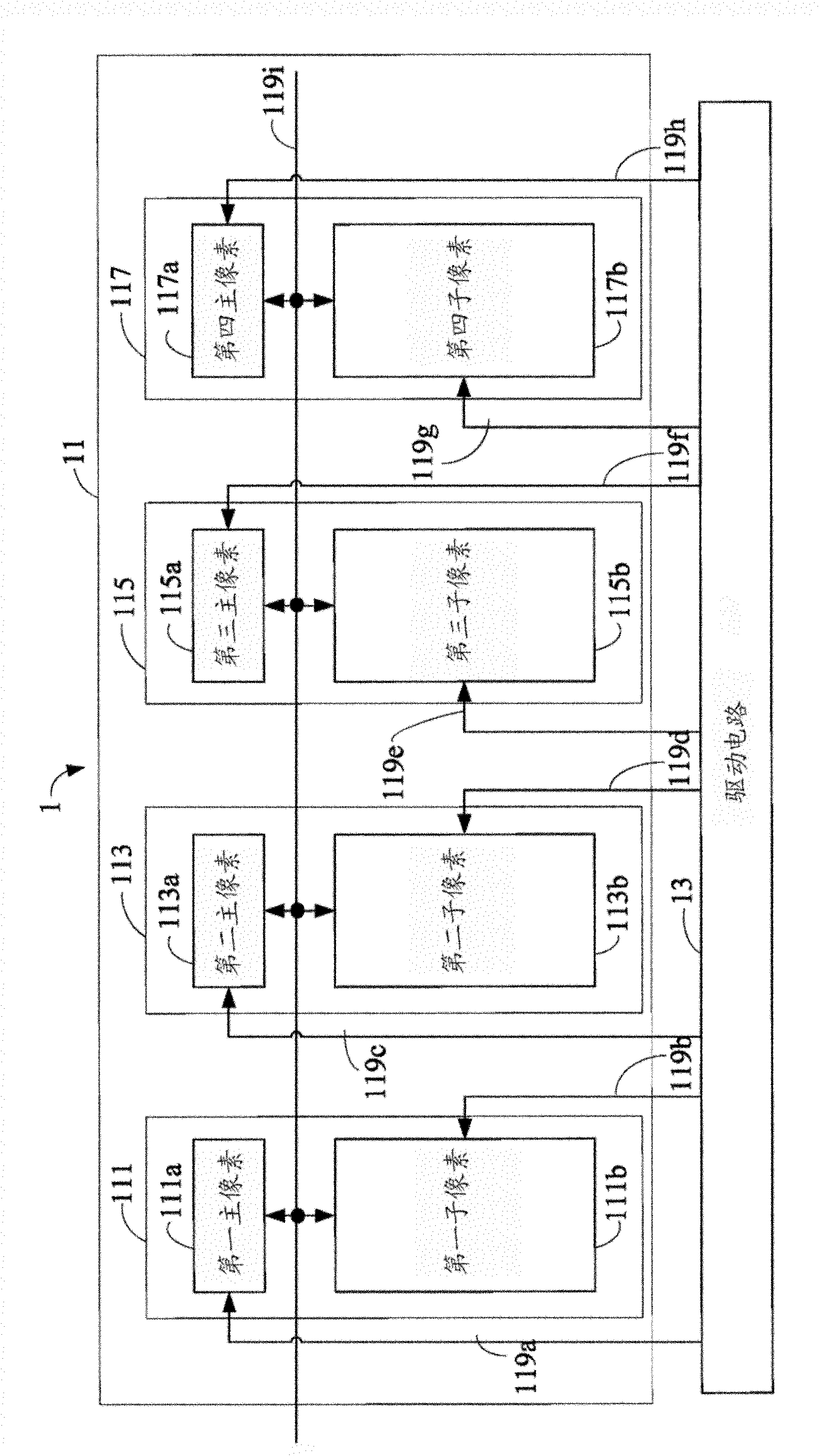
[0033] The first embodiment of the present invention is as image 3 As shown, it is a schematic diagram of a display 1, by image 3 It can be seen from the figure that the display 1 includes a pixel circuit 11 and a driving circuit 13, the pixel circuit 11...


PUM


Abstract

The invention relates to a display and a pixel circuit thereof. The display comprises the pixel circuit and a drive circuit, wherein the drive circuit is used for providing drive voltage to the pixel circuit; the pixel circuit belongs to two data lines one gate line (2D1G) architecture and at least comprises two pixel electrodes; and the two pixel electrodes belong to the same pixel type and are adjacent to each other. The pixel circuit can effectively solve the problem of color washout of specific display frames.

Description

technical field [0001] The invention relates to a display and its pixel circuit. Specifically, the present invention relates to a display device and a pixel circuit thereof having two adjacent pixel electrodes of the same pixel type. Background technique [0002] As liquid crystal displays continue to develop towards large-size display specifications, in order to overcome the viewing angle problem under large-size displays, the wide viewing angle technology of liquid crystal display panels must also continue to improve and break through. Among them, a multi-domain vertical alignment (MVA) liquid crystal display panel and a polymer stabilized alignment (PSA) liquid crystal display panel are currently common wide viewing angle technologies. [0003] In order to improve the color washout problem (color washout) in the liquid crystal display panel, an advanced multi-domain vertical alignment (Advanced-MVA) liquid crystal display panel has been proposed, which mainly divides eac...

Claims


Application Information

Patent Timeline
IPC IPC(8): G02F1/1362G02F1/133
Inventor 唐隆绫黄韦凯
Owner AU OPTRONICS CORP
Why Eureka
Try Eureka