Rotating electrical machine

A technology for rotating electrical machines and stator cores, applied in electrical components, electromechanical devices, electrical components, etc., can solve problems such as damage to insulating parts and short circuits, and achieve the effect of preventing damage to insulating parts

Active Publication Date: 2020-07-24
HONDA MOTOR CO LTD
View PDF18 Cites 0 Cited by
  • Summary
  • Abstract
  • Description
  • Claims
  • Application Information

AI Technical Summary

Problems solved by technology

As a result, the flanges of the teeth of the electromagnetic steel sheet 110A contact the insulating member such as the insulating film and insulating paper surrounding the coil from the radial direction, thereby damaging the insulating member and causing a short circuit.

Method used


Image

  • Rotating electrical machine
  • Rotating electrical machine
  • Rotating electrical machine

Examples


Embodiment Construction

[0073] Hereinafter, one embodiment of the rotating electric machine of the present invention will be described based on the drawings. The rotating electric machines of the present invention include at least electric generating and driving rotating electric machines.

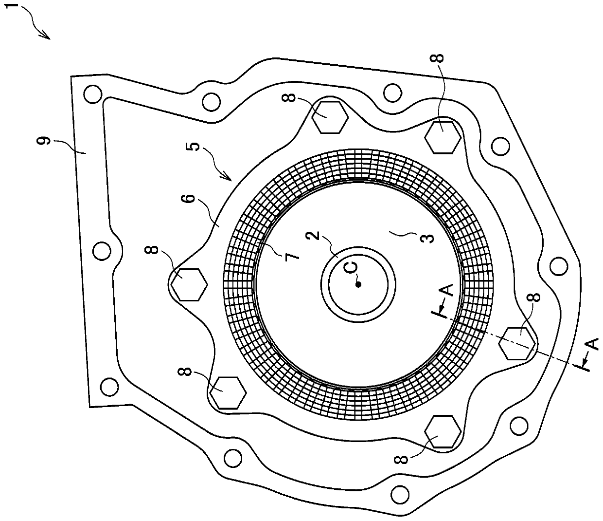
[0074] refer to Figure 1 to Figure 5 A rotating electrical machine 1 according to one embodiment of the present invention will be described. In the drawings, for ease of view, reference signs may be attached to only a part of portions having a plurality of identical attributes. In addition, when components have the same shape, structure, etc., in order to understand drawing easily, the same code|symbol may be attached|subjected, respectively.

[0075]

[0076] Such as figure 1 As shown, the rotating electric machine 1 includes a rotor 3 , a stator 5 , and a case 9 .

[0077] The rotor 3 has a rotor shaft 2 . There is a center axis C at the center of the rotor shaft 2 . The central axis C is parallel to ...


PUM


Abstract

The invention provides a rotating electrical machine capable of preventing damage to an insulating member and short circuit of a coil. The rotating electrical machine (1) is provided with: a stator (5) having a stator core (6) and a coil (7) attached to the stator core (6); a housing (9); and a fastening member (8) for fixing the stator (5) to the housing (9). The housing (9) is formed of a material having a higher coefficient of linear expansion than the stator core (6). A buffer plate (50) is inserted between a fastening part (40) of the stator core (6) and an abutting part (90) of the housing (9). The coefficient of friction between the buffer plate (50) and the fastening part (40) of the stator core (6) is less than the coefficient of friction between the buffer plate (50) and the abutting part (90) of the housing (9) and is less than or equal to the coefficient of friction between the fastening part (40) of the stator core (6) and the abutting part (90) of the housing (9).

Description

technical field [0001] The present invention relates to a rotating electrical machine mounted on an electric vehicle or the like. Background technique [0002] Conventionally, rotating electric machines have been used as power sources and power generation sources for vehicles such as hybrid cars. The rotary electric machine has a stator. [0003] For example, the rotating electrical machine of Patent Document 1 includes a stator including a stator core and coils. The stator core is formed into a ring shape by stacking a plurality of ring plates in the axial direction. The coil is surrounded by an insulating part such as a film or insulating paper. The attachment portion of the stator core is fixed to the case (stator supporting member) by bolts or the like, for example. [0004] The plurality of teeth are provided at intervals in the circumferential direction on the inner peripheral edge of the yoke portion. Slots for accommodating coils are formed between adjacent teet...

Claims


Application Information

Patent Timeline
IPC IPC(8): H02K1/18H02K3/52H02K3/34
CPCH02K1/18H02K3/522H02K3/345
Inventor 金田和弥
Owner HONDA MOTOR CO LTD
Why Eureka
Try Eureka