Force detection device and robot

A detection device and robot technology, applied in the direction of robots, manipulators, and the measurement of properties and forces using piezoelectric devices, etc., can solve problems such as large weight, small linear expansion coefficient, and redundancy

Active Publication Date: 2016-08-17
SEIKO EPSON CORP
View PDF9 Cites 4 Cited by
  • Summary
  • Abstract
  • Description
  • Claims
  • Application Information

AI Technical Summary

Problems solved by technology

[0009] However, in the force detection device described in Patent Document 1, the first plate and the second plate are entirely made of stainless steel, and since stainless steel has a small coefficient of linear expansion and a relatively high density on the contrary, there is a problem that it is heavy.
[0010] In addition, since it is necessary to maintain high detection accuracy of the force detection device, in order to reduce weight, as the material constituting the first plate and the material constituting the second plate, it is not possible to select only materials with low density.
[0011] In addition, in the force sensor described in Patent Document 2, since the wiring is drawn out from the outer peripheral portion of the force sensor, when the arm moves, pulling, bending, twisting, etc. occur in the wiring, thereby exerting unnecessary stress on the force sensor. force
As a result, there is a problem that an error occurs with respect to the force originally intended to be detected, and the detection accuracy decreases.

Method used


Image

  • Force detection device and robot
  • Force detection device and robot
  • Force detection device and robot

Examples


no. 1 approach

[0082]

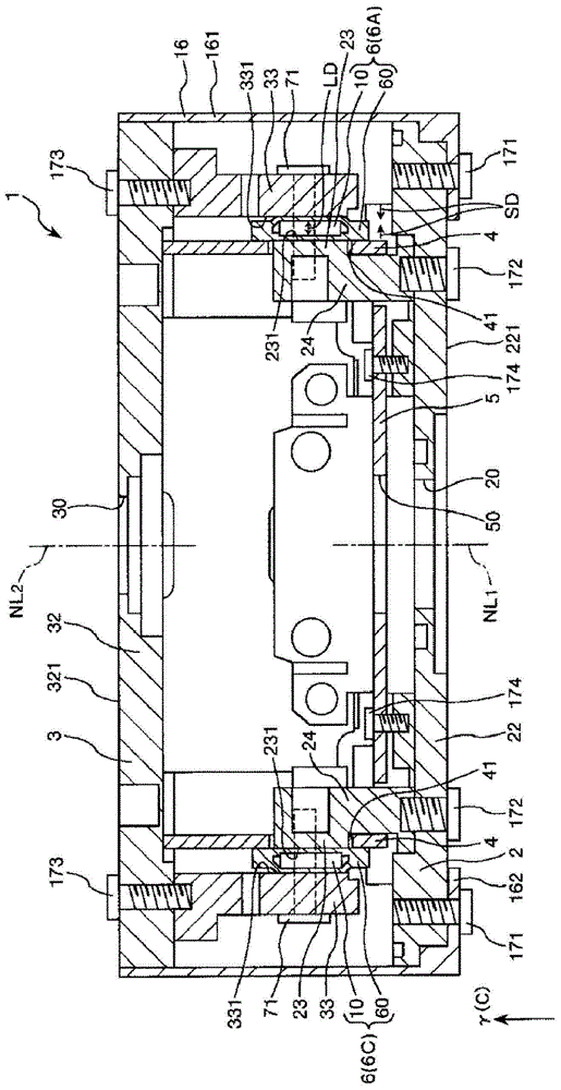
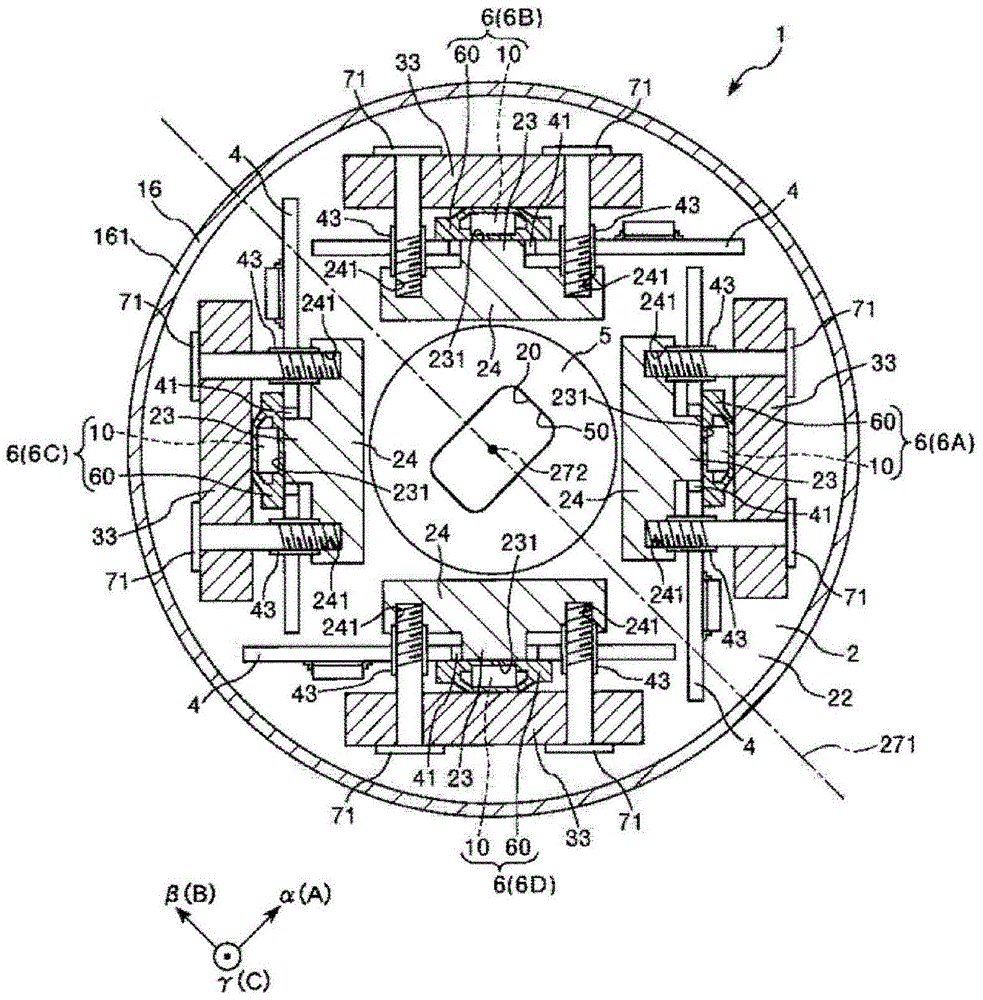
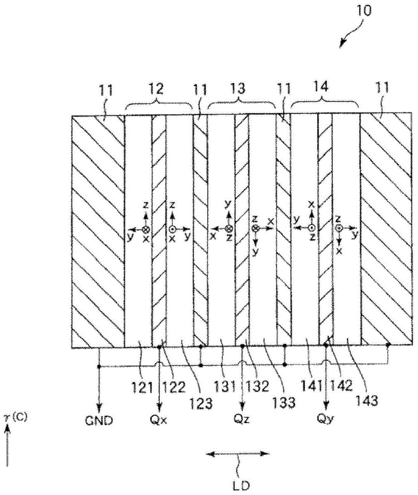
[0083] figure 1 It is a sectional view showing the force detection device of this embodiment. figure 2 yes figure 1 A cross-sectional view of the force detection device shown. image 3 is a brief representation figure 1 Cross-sectional view of the charge output element of the force-sensing device shown. Figure 4 is indicative figure 1 A diagram of the state where the force detection device is shown being heated. Figure 5 is indicative figure 1 In the force detection device shown, the first member of the first base and the third member of the second base are heated.

[0084] Additionally, the following, will figure 1 The upper side in is called "upper" or "upper", and the lower side is called "lower" or "below".

[0085] In addition, in figure 2 In FIG. 3 , an α axis, a β axis, and a γ axis are illustrated as three mutually orthogonal axes. In addition, in figure 1 , image 3 , of the three axes described above, only the γ axis is shown in the figure....

no. 2 approach

[0201]

[0202] Figure 6 is a cross-sectional view showing the force detection device of this embodiment ( Figure 7 BB line sectional view in). Figure 7 yes Figure 6 The cross-sectional view of the force detection device shown ( Figure 6 A-A line sectional view in). Figure 8 is to indicate that the Figure 6 A diagram of a case where the force detection device shown is applied as a force detection device of a robot. Figure 9 is to indicate that the Figure 6 A diagram of a case where the force detection device shown is applied as a force detection device of a robot. Figure 10 It is a diagram schematically showing a situation in which a conventional force detection device is applied as a force detection device for a robot. Figure 11 yes means Figure 9 A graph showing the output of the charge output element of the force sensing device. Figure 12 yes means Figure 10 A graph showing the output of the charge output element of the conventional force detection...


PUM

PropertyMeasurementUnit
densityaaaaaaaaaa
densityaaaaaaaaaa
densityaaaaaaaaaa

Abstract

The invention provides a force detection device and a robot. To obtain a force detection device and a robot light in weight and having excellent detection accuracy, The force detection device includes a first member, a second member joined to the first member, and a piezoelectric element joined to the second member. A material forming the first member is different from a material forming the second member. The first member is formed in a plate shape. The piezoelectric element and the second member are disposed at an end portion of the first member. A through-hole is formed in the center portion of the first member.

Description

technical field [0001] The invention relates to a force detection device and a robot. Background technique [0002] In recent years, industrial robots have been gradually introduced into production facilities such as factories for the purpose of improving production efficiency. This type of industrial robot is equipped with: an arm that can be driven with respect to one axis or multiple axes; and an end effector such as a hand attached to the end of the arm, a component inspection tool, or a component transfer tool, and can perform assembly of components. Parts manufacturing operations, parts handling operations, parts handling operations, and parts inspection operations, etc. [0003] In such an industrial robot, a force detection device (force sensor) is provided between the arm and the end effector. Since the force detection device is provided at the distal end of the arm, the weight of the force detection device occupies a part of the weight (capable load) that the rob...

Claims


Application Information

Patent Timeline
Patent Type & Authority Applications(China)
IPC IPC(8): G01L1/16
CPCG01L1/16B25J13/085B25J19/028Y10S901/46
Inventor 西村义辉水岛信幸神谷俊幸河合宏纪
Owner SEIKO EPSON CORP
Why Eureka
Try Eureka