Haptic feedback device

a haptic feedback and feedback technology, applied in the direction of mechanical control devices, manual control with single controlling member, instruments, etc., can solve the problems of motor inertia, difficult to switch quickly, difficult to make small incremental movements, etc., and achieve the effect of quickly changing the direction and quantity of haptic feedback

Inactive Publication Date: 2006-09-07
ULTRA ELECTRONICS LTD
View PDF3 Cites 48 Cited by
  • Summary
  • Abstract
  • Description
  • Claims
  • Application Information

AI Technical Summary

Benefits of technology

The invention has several advantages over the previous patent. Firstly, it uses a motor to actively move the output, providing more feedback options. Secondly, it uses a pair of clutches to quickly change the direction and quantity of haptic feedback, and can generate different types of movements like flutter or rumble.

Problems solved by technology

The patent text describes a haptic feedback device used in a vehicle steering system. The device uses either an electric motor or a magneto-rheological device to provide feedback to the driver. However, the use of a switched electric motor introduces the problem of motor inertia, which makes it difficult to switch quickly and make small incremental movements. MR devices, on the other hand, can provide a resistive damping force but have traditionally been limited to damping applications. Therefore, the technical problem of the patent text is to provide a haptic feedback device that overcomes the problem of motor inertia and can provide both resistive damping force and smooth feedback to the driver.

Method used


Image

  • Haptic feedback device
  • Haptic feedback device
  • Haptic feedback device

Examples


Embodiment Construction

)

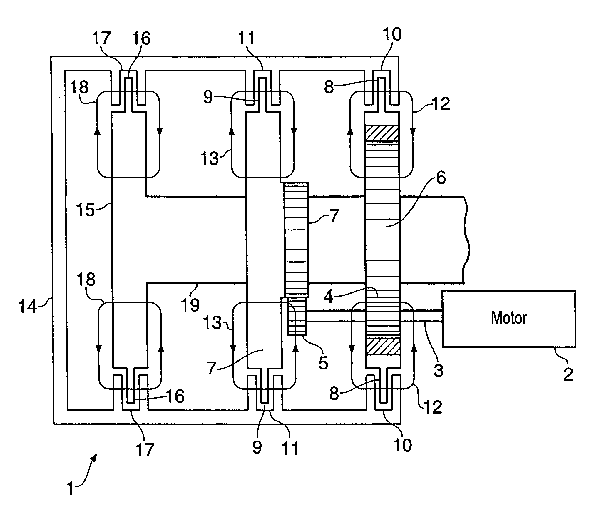
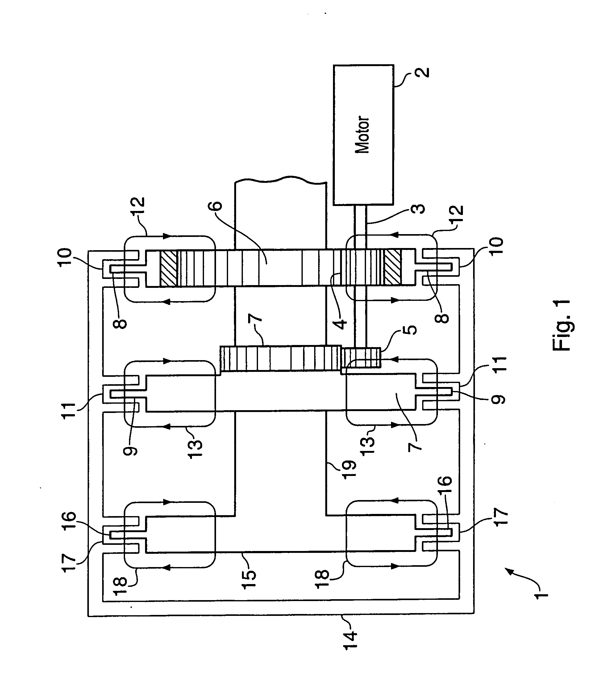
[0019] Referring to FIG. 1, a haptic feedback device 1 includes a motor 2 with a drive shaft 3 which rotates at a constant speed and direction. The drive shaft 3 carries first and second spur gears 4, 5. The first gear 4 drives the teeth on the inside of a ring gear 6. The second gear 5 drives the teeth on the outside of a spur gear 7. Thus, the motor 2 constantly drives the ring gear 6 in one direction, and the spur gear 7 in the opposite direction. The gears 6, 7 are configured to run at the same rotational speed.

[0020] An output element 14 has three pairs of annular flanges which each define respective slots 10, 11, 17. The gears 6, 7 have annular flanges 8, 9 which are each received in a respective one of the slots 10, 11. The slots 10, 11, 17 contain a magneto-rheological fluid such as Lord MRF-132AD. The fluid just fills the slots 10, 11, 17 which are about 1.7 mm wide and so very little fluid is required. Seals (not shown) are provided. The seals can be either dynamic (rota...


PUM


Abstract

A haptic feedback device is described for providing feedback to a user. The device includes a motor, an output element and a pair of magneto-rheological clutches for selectively coupling the motor with the output element. The pair of clutches are configured to drive the coupled element in opposite directions. The device may be provided in a steering wheel or similar.

Description


Claims


Application Information

Patent Timeline
Owner ULTRA ELECTRONICS LTD
Why Eureka
Try Eureka