Systems and methods for the reduction of peak to average signal levels of multi-bearer single-carrier and multi-carrier waveforms

a multi-bearer and waveform technology, applied in the field of electronic systems, can solve the problems of reducing the efficiency of the rf amplifier, affecting the cost and size of the radio frequency amplifier affecting the cost of the base station, so as to reduce the peak to average ratio of the multi-bearer waveform and the cost

Inactive Publication Date: 2006-09-07
MAXLINEAR ASIA SINGAPORE PTE LTD
View PDF35 Cites 12 Cited by
  • Summary
  • Abstract
  • Description
  • Claims
  • Application Information

AI Technical Summary

Benefits of technology

[0012] Embodiments of the present invention include apparatus and methods that overcome the disadvantages of the prior art by manipulating a multibearer waveform, which can include single carrier or multiple carrier waveforms that reduce the peak to average ratio of the multibearer waveform. Advantageously, embodiments of the present invention allow radio frequency (RF) base stations to be more efficient, compact, and lower in cost than conventional base stations.
[0013] Embodiments of the invention permit significant reduction to the cost to provision digital and analog signal processing chains in communication systems. Embodiments of the invention may be applied to a variety of communications systems including both wire and wireless communications systems such as cellular, personal communications service (PCS), local multipoint distribution systems (LMDS), and satellite systems.

Problems solved by technology

As a result, the base station is significantly overdesigned, which results in a significant increase to the cost of the base station.
In particular, the cost and the size of the radio frequency (RF) amplifier of the base station are deleteriously affected.
For example, such an approach disadvantageously lowers the efficiency of the RF amplifier, as a higher powered RF amplifier will waste significantly larger amounts of power for biases and the like.
Further, the extra power dissipation is correspondingly dissipated with larger and more costly heat management techniques.
However, conventional hard limiting techniques are impractical because hard limiting generates distortion energy, which causes interference in adjacent channels.

Method used


Image

  • Systems and methods for the reduction of peak to average signal levels of multi-bearer single-carrier and multi-carrier waveforms
  • Systems and methods for the reduction of peak to average signal levels of multi-bearer single-carrier and multi-carrier waveforms
  • Systems and methods for the reduction of peak to average signal levels of multi-bearer single-carrier and multi-carrier waveforms

Examples


Embodiment Construction

[0041] Although this invention will be described in terms of certain preferred embodiments, other embodiments that are apparent to those of ordinary skill in the art, including embodiments which do not provide all of the benefits and features set forth herein, are also within the scope of this invention. Accordingly, the scope of the present invention is defined only by reference to the appended claims.

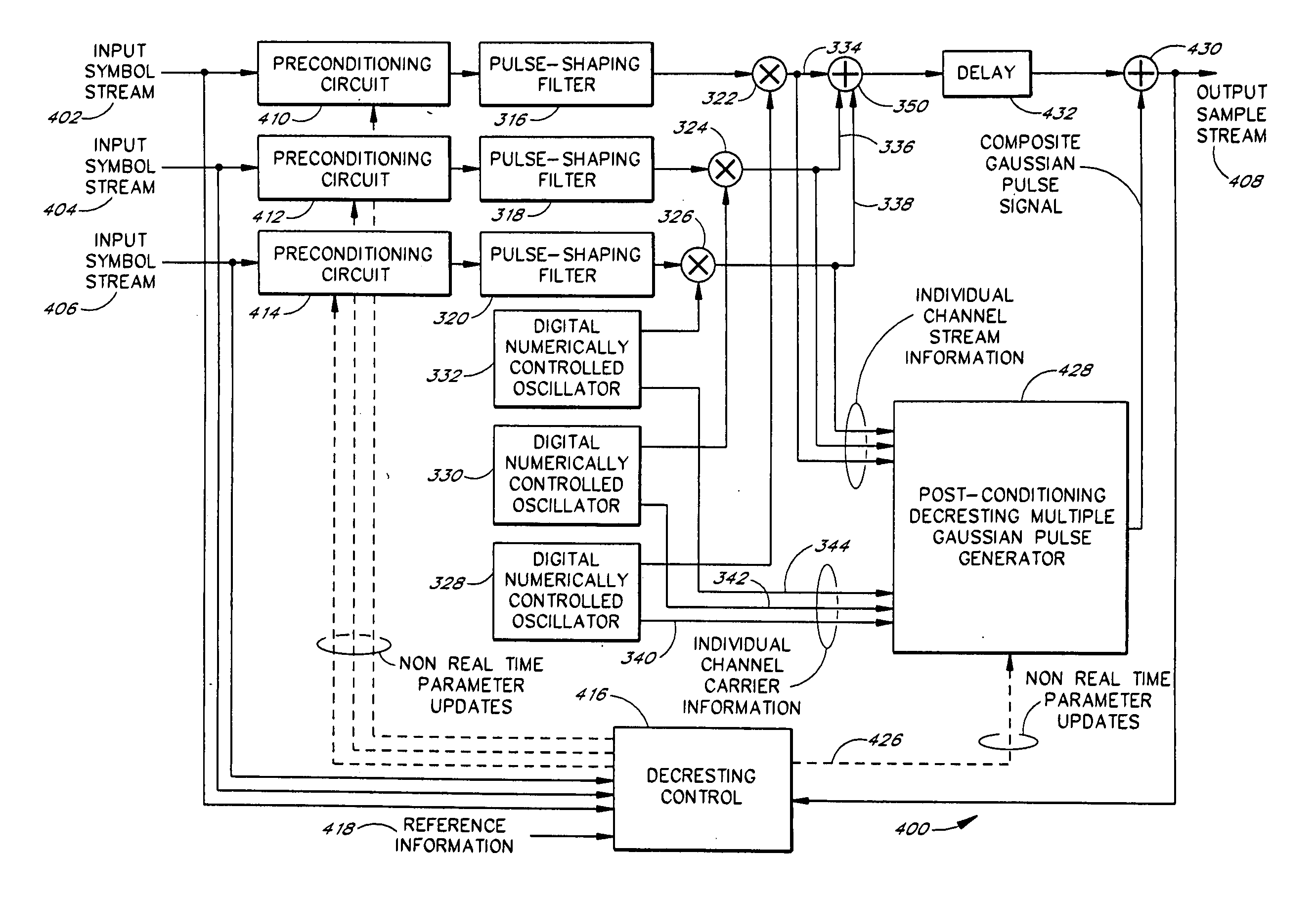
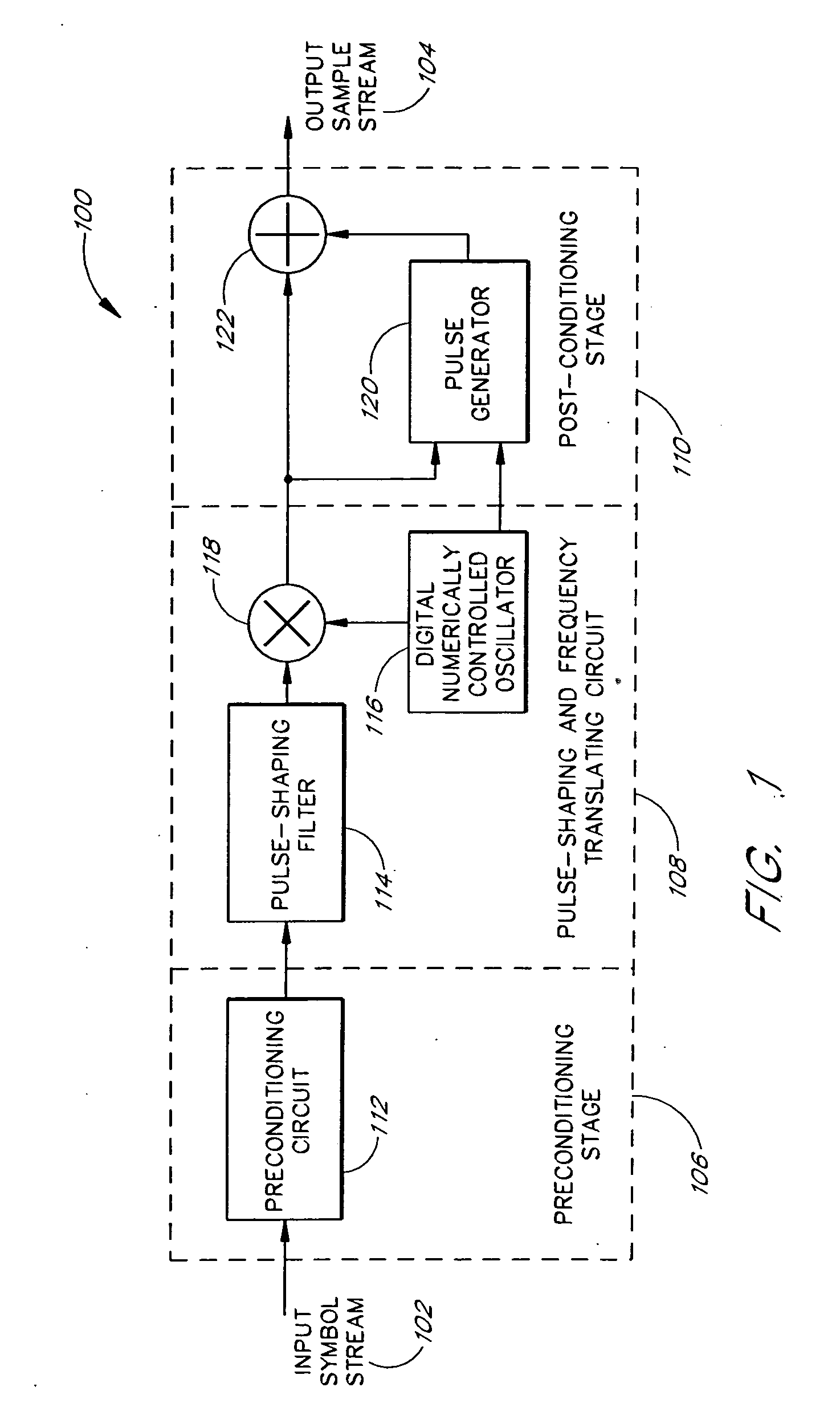
[0042]FIG. 1 illustrates a waveshaping circuit 100 according to one embodiment of the present invention. A waveshaping circuit can be adapted to shape either single data streams or multiple input streams with multiple baseband signals. The waveshaping circuit 100 shown in FIG. 1 is adapted to shape a single input data stream to a single shaped output data stream. Other embodiments that are adapted to shape and to combine multiple input signals to a shaped output data stream are described later in connection with FIGS. 3, 4, 9, 10, 15, 16, and 17.

[0043] An input symbol stream 102 is ...


PUM


Abstract

The present invention is related to methods and apparatus that can advantageously reduce a peak to average signal level exhibited by single or by multicarrier multibearer waveforms. Embodiments of the invention further advantageously can manipulate the statistics of the waveform without expanding the spectral bandwidth of the allocated channels. Embodiments of the invention can be applied to either multiple carrier or single carrier systems to constrain an output signal within predetermined peak to average bounds. Advantageously, the techniques can be used to enhance the utilization of existing multicarrier RF transmitters, including those found in third generation cellular base stations. However, the peak to average power level managing techniques disclosed herein can apply to any band-limited communication system and any type of modulation. The techniques can apply to multiple signals and can apply to a wide variety of modulation schemes or combinations thereof.

Description

RELATED APPLICATIONS [0001] This application is a continuation application of U.S. application No. 09 / 910,477, filed Jul. 20, 2001, which claims the benefit under 35 U.S.C. § 119(e) of U.S. Provisional Application No. 60 / 220,018, filed Jul. 21, 2000, the disclosures of which are hereby incorporated by reference in their entireties herein. [0002] This application is also related to a co-pending and commonly-owned patent application with application Ser. No. 09 / 910,422, filed on Jul. 20, 2001, and to a continuation application of the application Ser. No. 09 / 910,422, with application Ser. No. ______, filed on the same day as the present application, the disclosures of which are hereby incorporated by reference in their entireties herein.BACKGROUND OF THE INVENTION [0003] 1. Field of the Invention [0004] The present invention generally relates to electronics. In particular, the present invention relates to communications systems. [0005] 2. Description of the Related Art [0006] The rapid...

Claims


Application Information

Patent Timeline
Patent Type & Authority Applications(United States)
IPC IPC(8): H04L25/03H04L27/26
CPCH04L25/03834H04L27/2614H04L27/2624
Inventor WRIGHT, ANDREW S.RYAN, RICHARD E.KLIJSEN, BARTHOLOMEUS T. W.PEREGRYM, DENIS JOHNDAVISON, BRENDA
Owner MAXLINEAR ASIA SINGAPORE PTE LTD
Why Eureka
Try Eureka