Radiographic inspection of airframes and other large objects

a technology for airframes and other large objects, applied in the field of radiographic inspection, can solve problems such as blurred images, difficulty in positioning detectors in contact with the inspected structure, and reduced ability to discern defects

Inactive Publication Date: 2006-09-07
GENERAL ELECTRIC CO
View PDF20 Cites 16 Cited by
  • Summary
  • Abstract
  • Description
  • Claims
  • Application Information

AI Technical Summary

Problems solved by technology

It is often difficult to position these detectors in contact with the inspected structure.
This results in blurred images and reduced ability to discern defects.
This extended reach device may have significant motion at the end of the boom, including vibration and harmonic motion from the residual inertia after movement of the device.
Further, the large objects themselves often move during imaging.
This may be due to wind, personnel working on the aircraft, and the like.

Method used


Image

  • Radiographic inspection of airframes and other large objects
  • Radiographic inspection of airframes and other large objects
  • Radiographic inspection of airframes and other large objects

Examples


Embodiment Construction

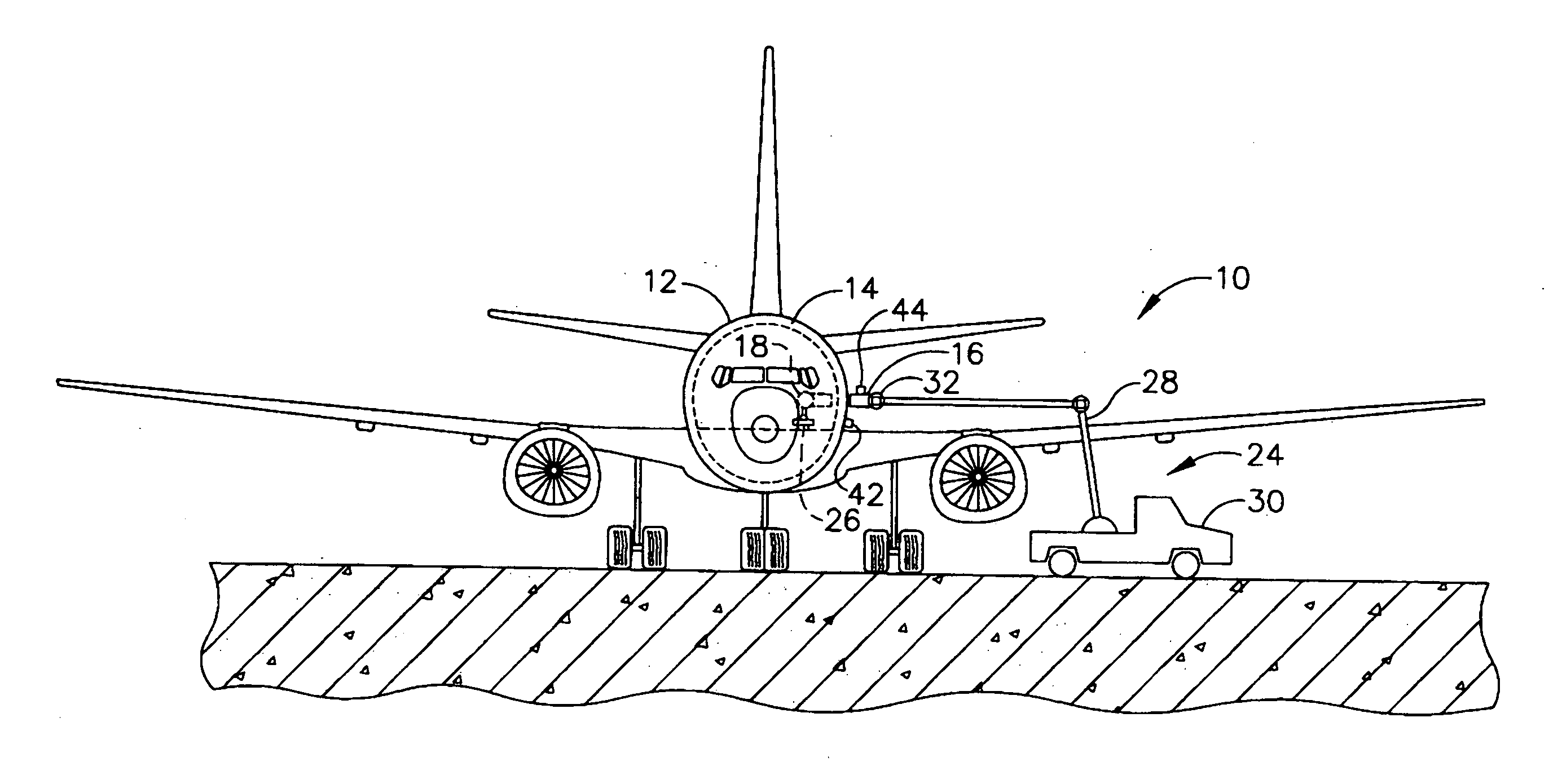
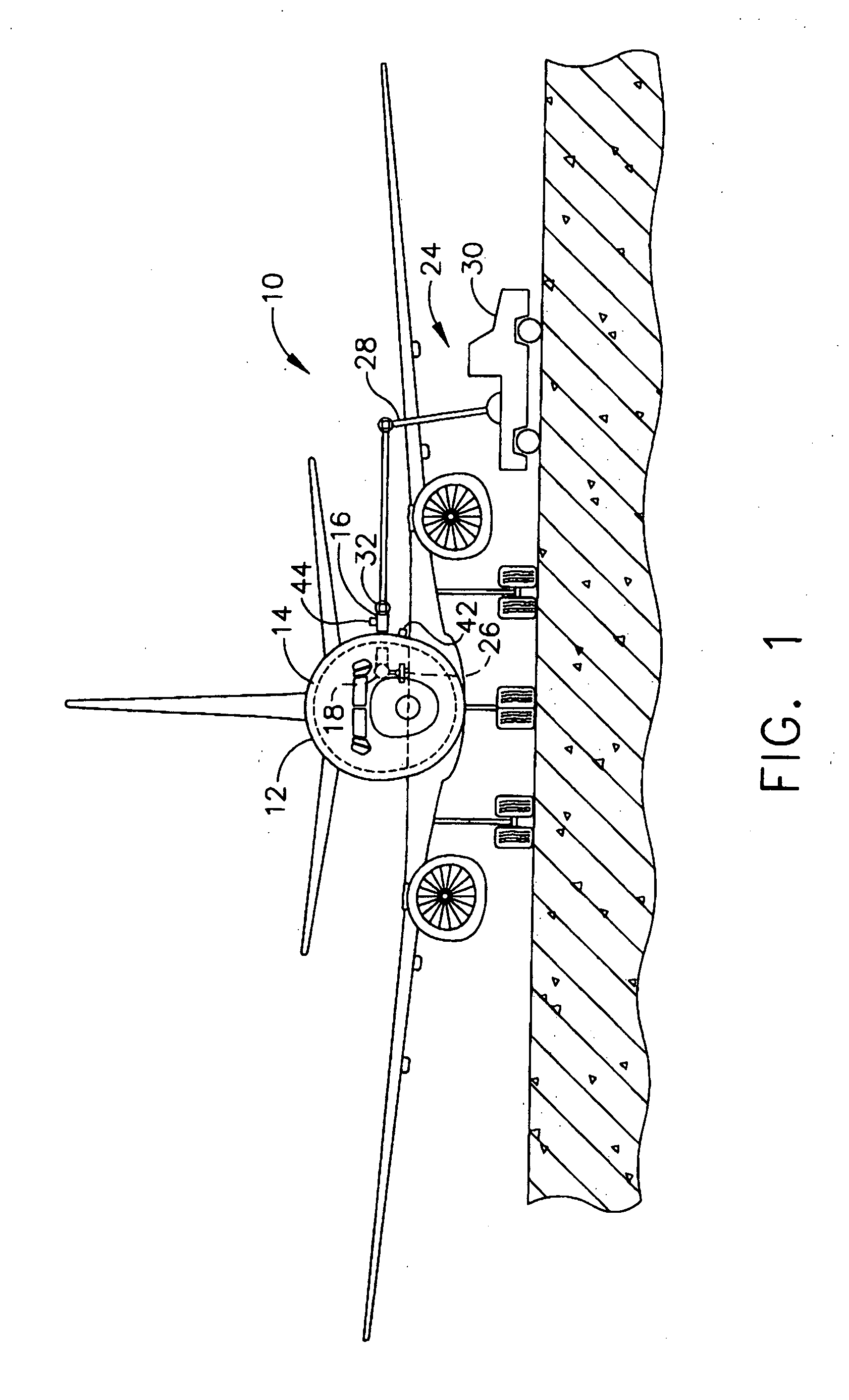
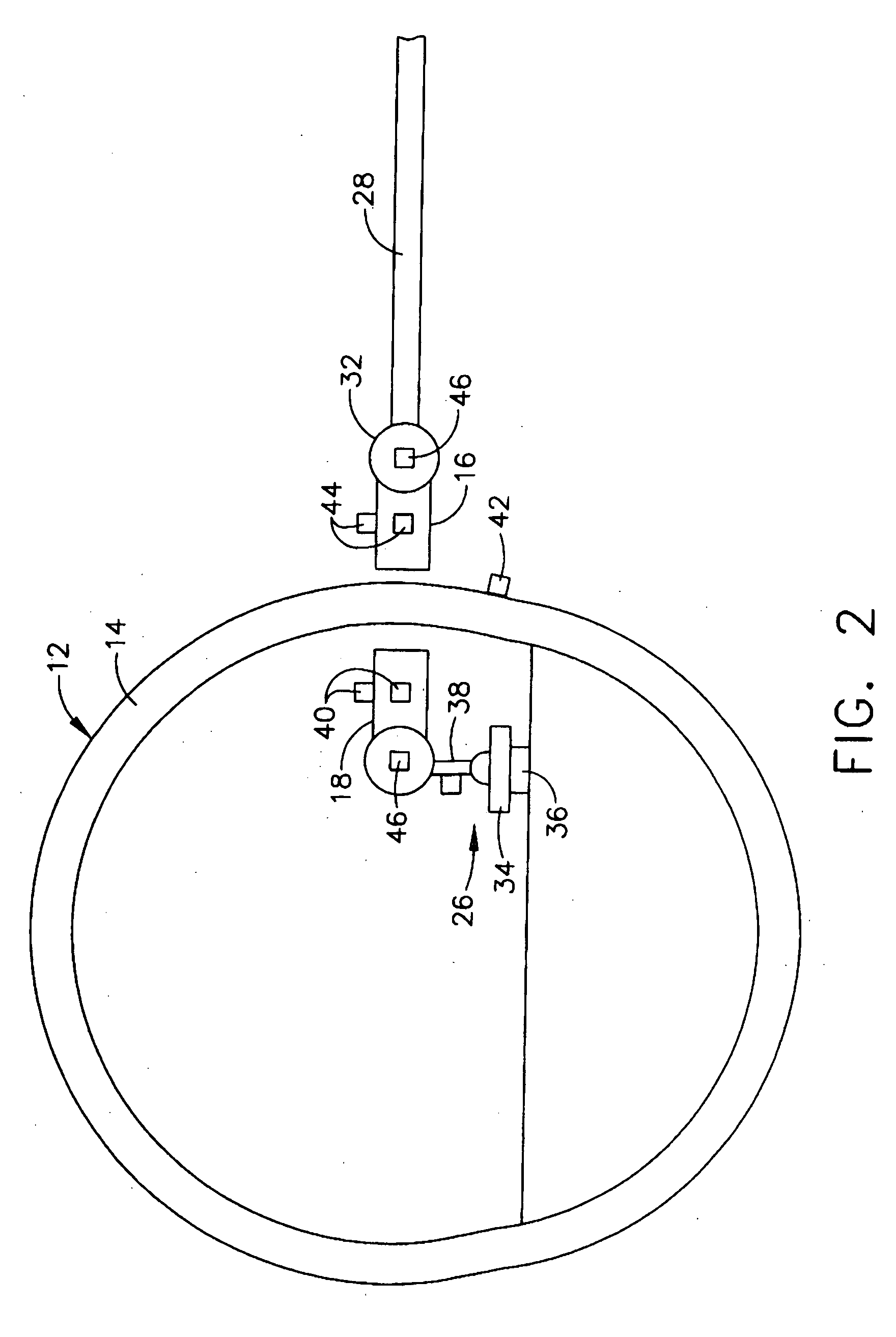
[0013] Referring to the drawings wherein identical reference numerals denote the same elements throughout the various views, FIG. 1 illustrates schematically a radiographic inspection system 10 for inspecting an aircraft fuselage 12. The fuselage 12 generally comprises a cylindrical wall 14 made up of a grid of circumferential frame members and longitudinal stringers covered by a skin of lightweight sheet metal. The inspection system 10 may be used with other types of structures as well. The inspection system 10 includes a radiation source 16 located on a first side of the fuselage wall 14 and a radiation detector 18 located on a second, opposite side of the fuselage wall 14. The radiation source 16 and radiation detectors 18 are relatively situated on opposite sides of the wall 14 so that radiation emitted by the radiation source 16 irradiates the fuselage wall 14 and then impinges on the radiation detector 18. As depicted in FIG. 1, the radiation source 16 is located outside of th...


PUM


Abstract

A system for radiographic inspection of an object includes a radiation source located on one side of the object and a radiation detector located on another side of the object, being positioned to receive radiation from the radiation source. At least one motion sensor is associated with the radiation detector, the radiation source, or the object, for detecting motion. The magnitude of motion of the components is compared to a pre-established limit value. The imaging process is conducted when the magnitude of any motion is less than the limit value.

Description

BACKGROUND OF THE INVENTION [0001] This invention relates generally to radiographic inspection and more particularly to a method of radiographic inspection of large objects such as airframes. [0002] Aircraft, including their fuselages and nacelles, and other large structures, often require periodic inspection to verify their structural condition. This may be done visually or with non-destructive evaluation (NDE) techniques. Because of the complicated physical structure of aircraft fuselages and nacelles, radiographic inspection, such as X-ray inspection, is used to avoid the disassembly of overlapping components, insulation, wall coverings, etc. Modern digital electronic detectors are replacing X-ray film in many X-ray inspection applications. It is often difficult to position these detectors in contact with the inspected structure. Thus the detector and the structure are often not in physical contact and do not always move together. This results in blurred images and reduced abilit...

Claims


Application Information

Patent Timeline
Patent Type & Authority Applications(United States)
IPC IPC(8): H05G1/00
CPCG01N23/04
Inventor BIRDWELL, THOMAS WILLIAMBANTEL, THOMAS EDWARD
Owner GENERAL ELECTRIC CO
Why Eureka
Try Eureka