Low profile, handle-in-between surgical scissors clamp

a surgical scissors and handle technology, applied in the field of surgical tools, can solve the problems of obstructing access to the surgical site, adding unnecessary time and expense to the surgical procedure, and affecting the operation, and achieves the effects of minimal overclearance, minimal underclearance, and minimal overclearan

Inactive Publication Date: 2006-09-07
MINNESOTA SCI
View PDF29 Cites 93 Cited by
  • Summary
  • Abstract
  • Description
  • Claims
  • Application Information

AI Technical Summary

Benefits of technology

[0010] The present invention is a clamp and a support system using the clamp. The clamp has a first clamping opening for receiving the support frame rod and second clamp opening for receiving the retractor or tool shaft. A handle controls operation of at least one and preferably both of the clamp members. In one aspect, the handle is always in line with one of the support frame rod and the retractor shaft, enabling tightening with a single handed scissors action. In another aspect, the handle is attached to the clamp at a location between the first and second clamping openings. In another aspect, the clamp is very low profile and positioned for minimal interference with the surgical arena, providing minimal underclearance for the support frame rod, and minimal overclearance for the retractor shaft, and minimal height separation between the support frame rod and the retractor shaft. In another aspect, the handle can be moved from a loosened position to a tightened position with a balanced, single hand application, enabled in part by use of a clamping force provided by a slide pin.

Problems solved by technology

Having to disassemble at least a portion of the surgical support apparatus about a surgical site to add additional retractors adds unnecessary additional time and expense to the surgical procedure.
Because the second U-shaped structure and the handle are located above the surgical support frame, the second U-shaped structure and the handle may obstruct access to the surgical site during some surgical procedures.
Surgical retractor systems must be robust and strong, as even a slight possibility of failure during use is not tolerated.

Method used


Image

  • Low profile, handle-in-between surgical scissors clamp
  • Low profile, handle-in-between surgical scissors clamp
  • Low profile, handle-in-between surgical scissors clamp

Examples


Embodiment Construction

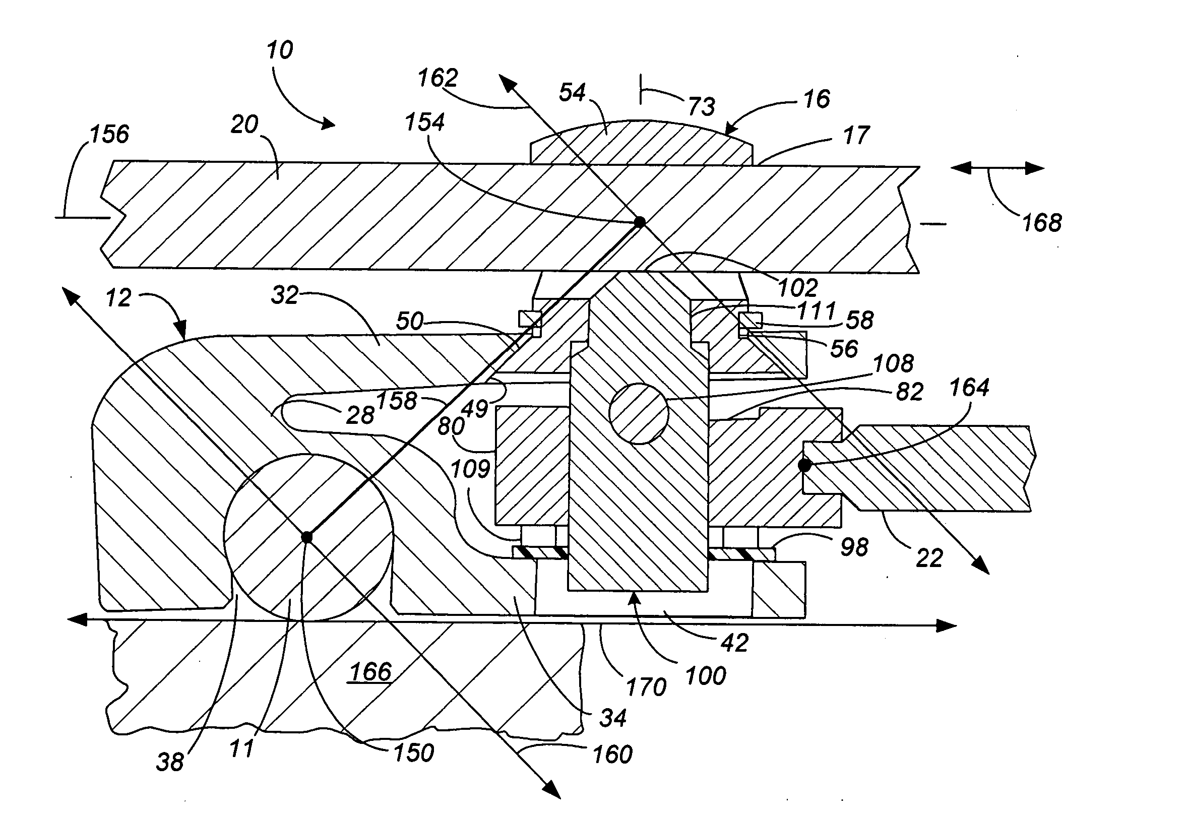
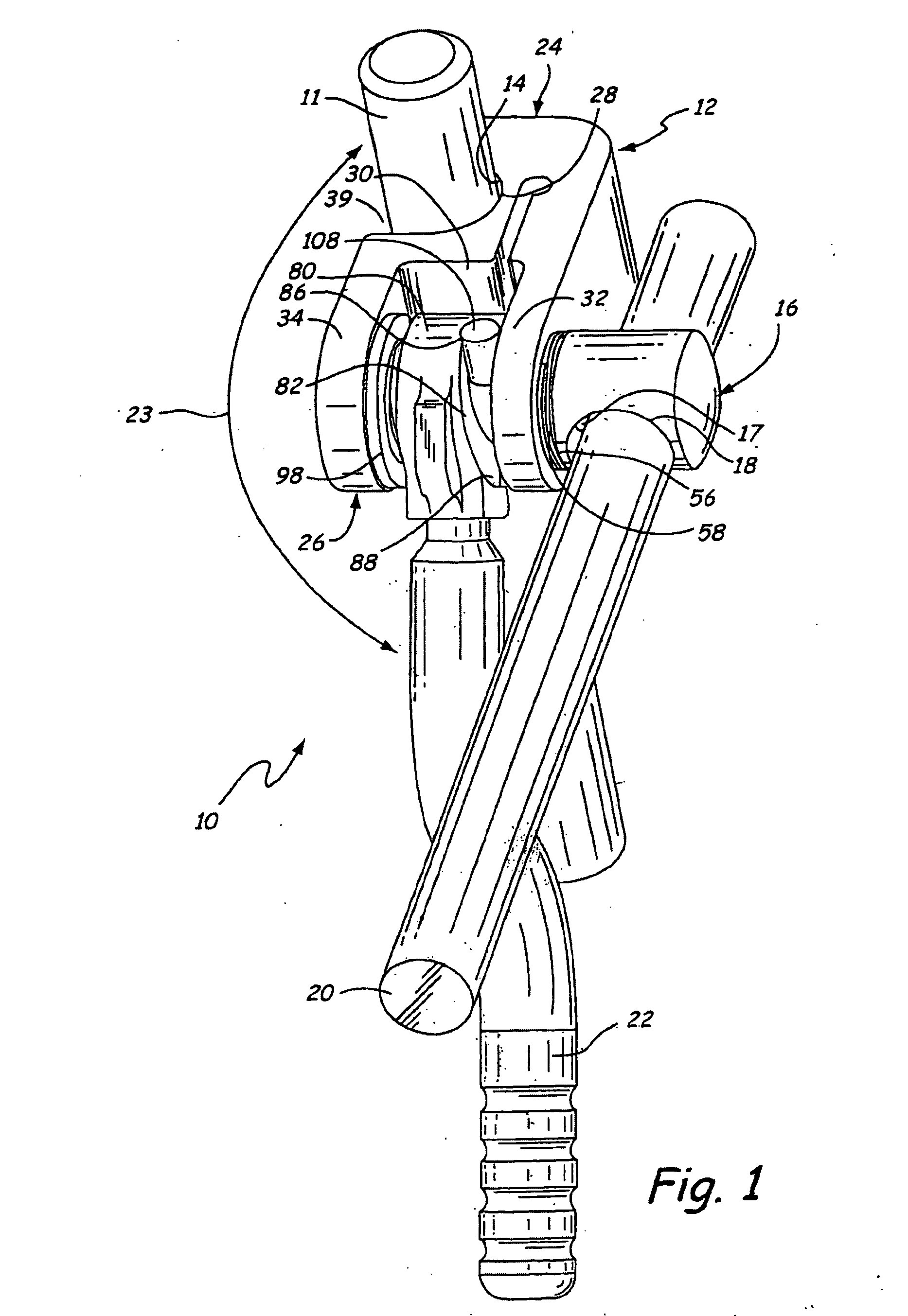
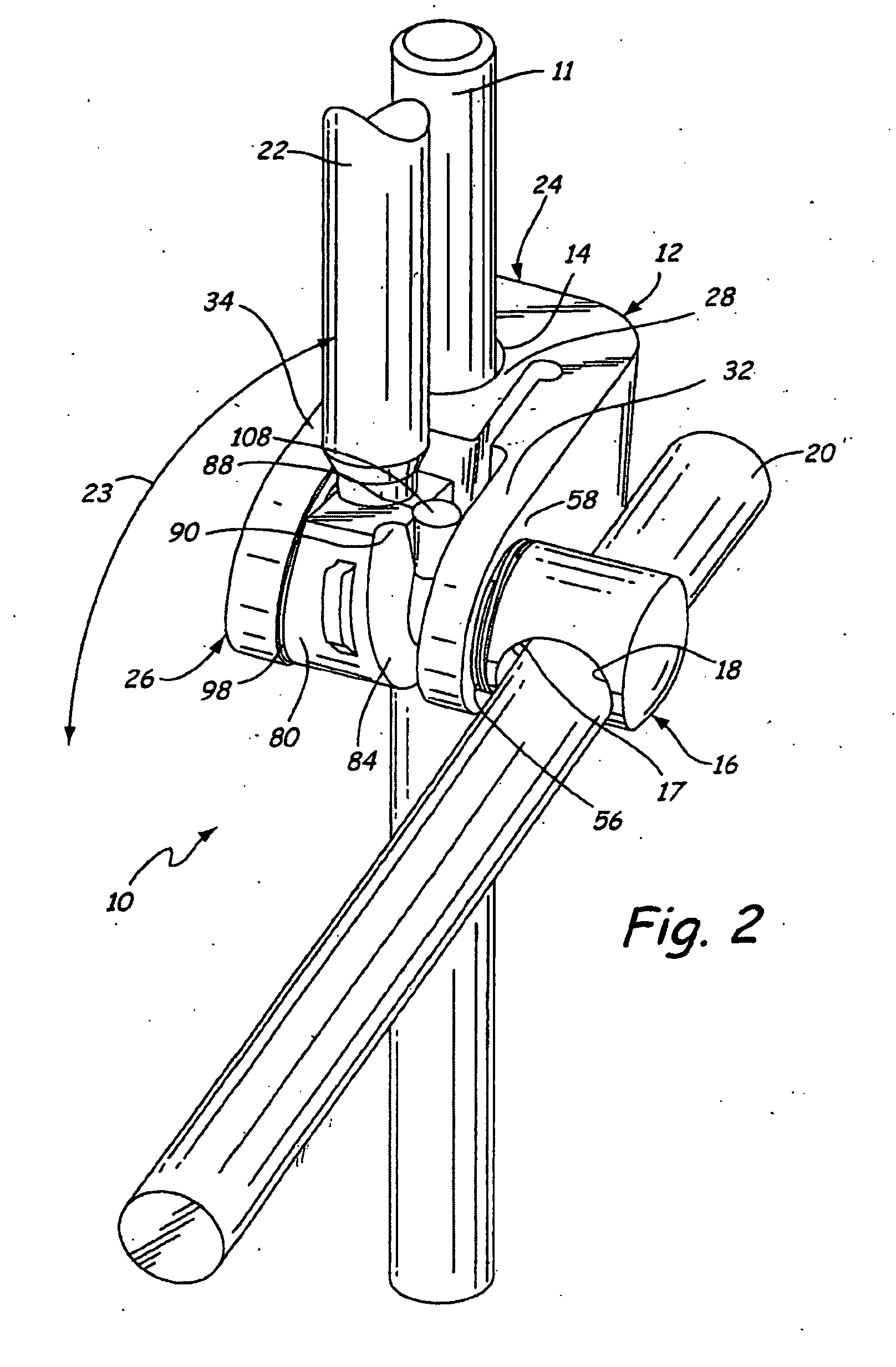
[0027] The present invention includes a low profile surgical clamp generally illustrated in FIG. 1 at 10. The clamp 10 is particularly suited for mounting a retractor (not shown) with respect to an operating table (not shown). The clamp 10 includes a first clamping member 12 having a first clamping surface 14 and a second clamping member 16 having a second clamping surface 18. In some aspects of the invention, other components may be substituted for the second clamping member 16 such as, but not limited to, permanently attached retractors, or retractors that are attached using other types of clamps or fasteners.

[0028] To position the clamp 10 within the surgical site, a clamping end 24 of the first clamping member 12 is positioned proximate a bar of a retractor support system, such as a retractor support arm 11. The first clamping surface 14 proximate the clamping end 24 is disposed about a portion of the retractor support arm 11.

[0029] The first clamping member 12 also includes a...


PUM


Abstract

A surgical clamp includes a first clamping member comprising a first clamping surface for engaging a first surgical rod and an attachment end. A second clamping member is mounted with respect to the first clamping member wherein the second clamping member comprises a second clamping surface for engaging a second surgical rod. A slide pin is disposed through and positioned within the attachment end of the first clamping member and wherein the shaft is in communication with the second clamping member. A force providing mechanism is disposed between the first and second clamping members and disposed about the slide pin wherein when the force providing mechanism and the slide pin are movable with respect to each other and place the first and second clamping members in either a loosened position or a tightened position.

Description

CROSS-REFERENCE TO RELATED APPLICATION(S) [0001] This is a continuation-in-part of application Ser. No. 10 / 664,195 of Bjork et al. filed Sep. 17, 2003 and entitled FULCRUM WEDGE CLAMP, the content of which is hereby incorporated by reference in its entirety. This is also a continuation-in-part of application Ser. No. 10 / 732,491 of Bjork et al. filed on Dec. 10, 2003 and entitled FULCRUM WEDGE CLAMP, the content of which is hereby incorporated by reference in its entirety, which is a continuation of application Ser. No. 10 / 664,195. This application is also a continuation-in-part of application Ser. No. 11 / 034,231 of Bjork et al., filed Jan. 12, 2005 and entitled THREADED FULCRUM CLAMP, the contents of which is hereby incorporated by reference in its entirety, which is a continuation-in-part of application Ser. No. 10 / 732,491 and claims priority from Provisional Application No. 60 / 535,910 filed on Jan. 12, 2004.BACKGROUND OF THE INVENTION [0002] The present invention relates generally...

Claims


Application Information

Patent Timeline
Patent Type & Authority Applications(United States)
IPC IPC(8): A61B1/32
CPCA61B1/00149A61B17/0206A61B19/26A61B2019/267A61B90/57A61B90/50
Inventor BJORK, TODD M.SHARRATT, TODD WILLIAMBERG, CHRISTOPHER LEE
Owner MINNESOTA SCI
Why Eureka
Try Eureka