This helps you quickly interpret patents by identifying the three key elements:
Problems solved by technology
Method used
Benefits of technology
Benefits of technology
[0012] The present invention has been made in consideration of the above problems, and an object thereof is the provision of an interlabial pad that can be made to fit a vaginal opening and a vestibule floor without a gap with the vaginal opening or the vestibule floor occurring, the pad enabling leakage of menstrual blood from a gap to be prevented, and dropping out of the pad to be avoided, when a wearer wears the pad between labia.
Problems solved by technology
Moreover, in the case of tampons, due to product attributes thereof, a foreign objectsensation or a feeling of discomfort when worn, or difficulty in fitting inside the vagina occurs, and considerable efforts have been made to eliminate these.
However, since the interlabial pad adheres to the body due to interlabial sandwiching force, it has to flexibly follow movements of the labia to the left and right caused by the wearer's movements.
In cases in which it is difficult for the interlabial pad to follow the body movements, there is a danger that it may drop out of the wearer's labia.
Furthermore, if the pad is forcibly inserted so as to fit the central axis in the longitudinal direction of the pad, with the vaginal opening and the vestibule floor, there has been a risk that the pad, having uniform rigidity in its longitudinal direction, may buckle irregularly and contact with the labia inner wall may deteriorate, so that the pad may drop down from the labia, and also there has been a risk that excessive irritation may be given to the labia.
Method used
Image
Click on the blue label to locate the original text in one second.
Reading with bidirectional positioning of images and text.
Examples
embodiment 1
Overall Configuration of Interlabial Pad
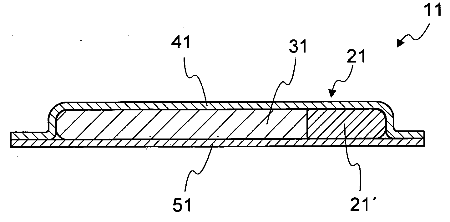
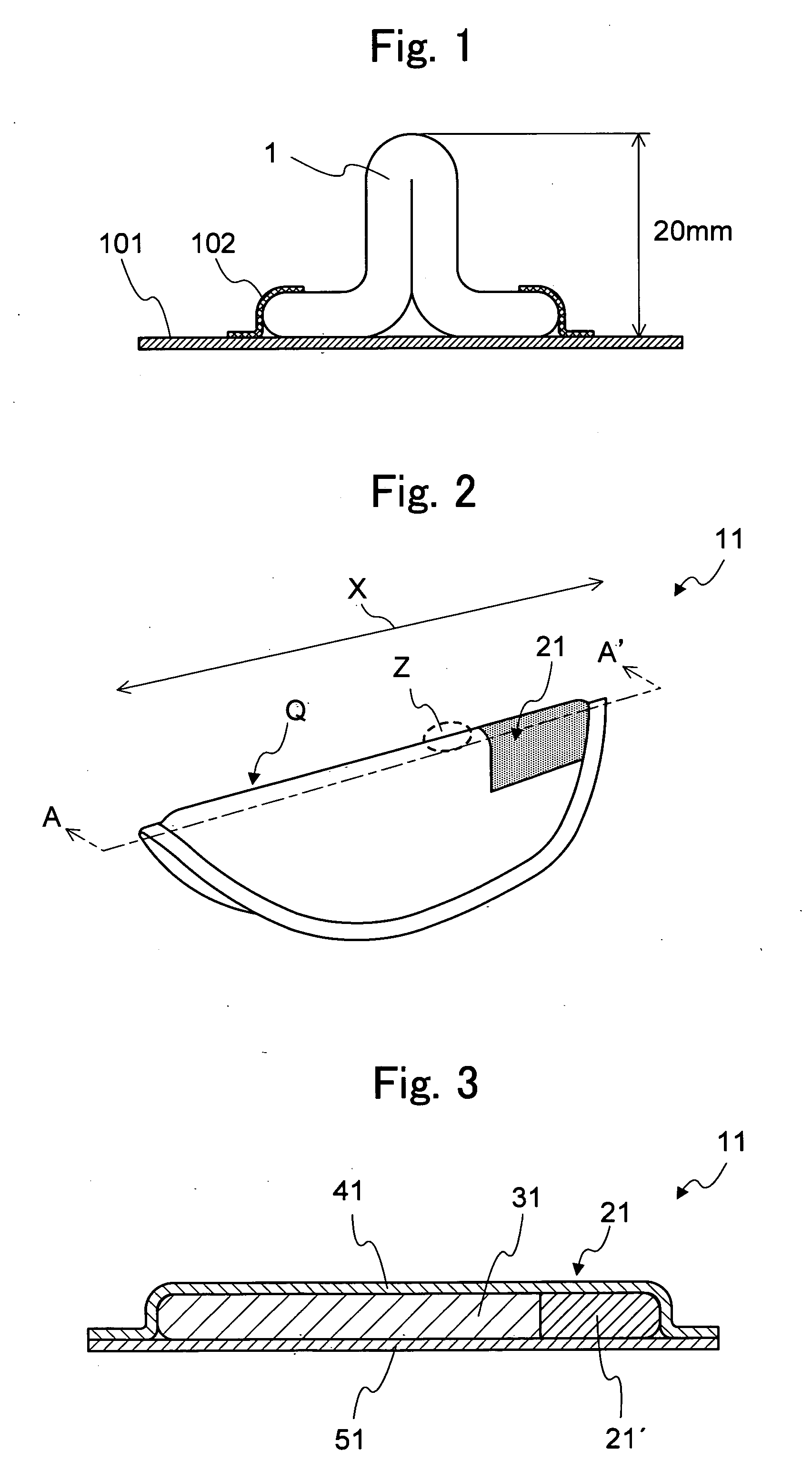
[0057]FIG. 2 is a perspective view of an interlabial pad 11 relating to Embodiment 1, folded in two. The interlabial pad 11 of the present embodiment has a central axis Q extending along a longitudinal direction X. The pad 11 is folded in two, with the central axis Q as a folding line, and is worn with at least one portion held between labia minora of the labia, so that at least one portion close to the central axis Q touches a vestibule floor inside the labia. In addition, the pad 11 is provided with a rear portion low compression rigidity structure, by which the rear portion that is positioned to the rear of a wearer, and that touches the body of the wearer first when worn, has low compression rigidity in comparison to a front portion positioned to the front, so that the rear portion of the pad has a low compression rigidity portion 21.
[0058]FIG. 3 is a cross-sectional view of FIG. 2 at A-A′. As shown in FIG. 3, the interlabial pad 11 of ...
embodiment 2
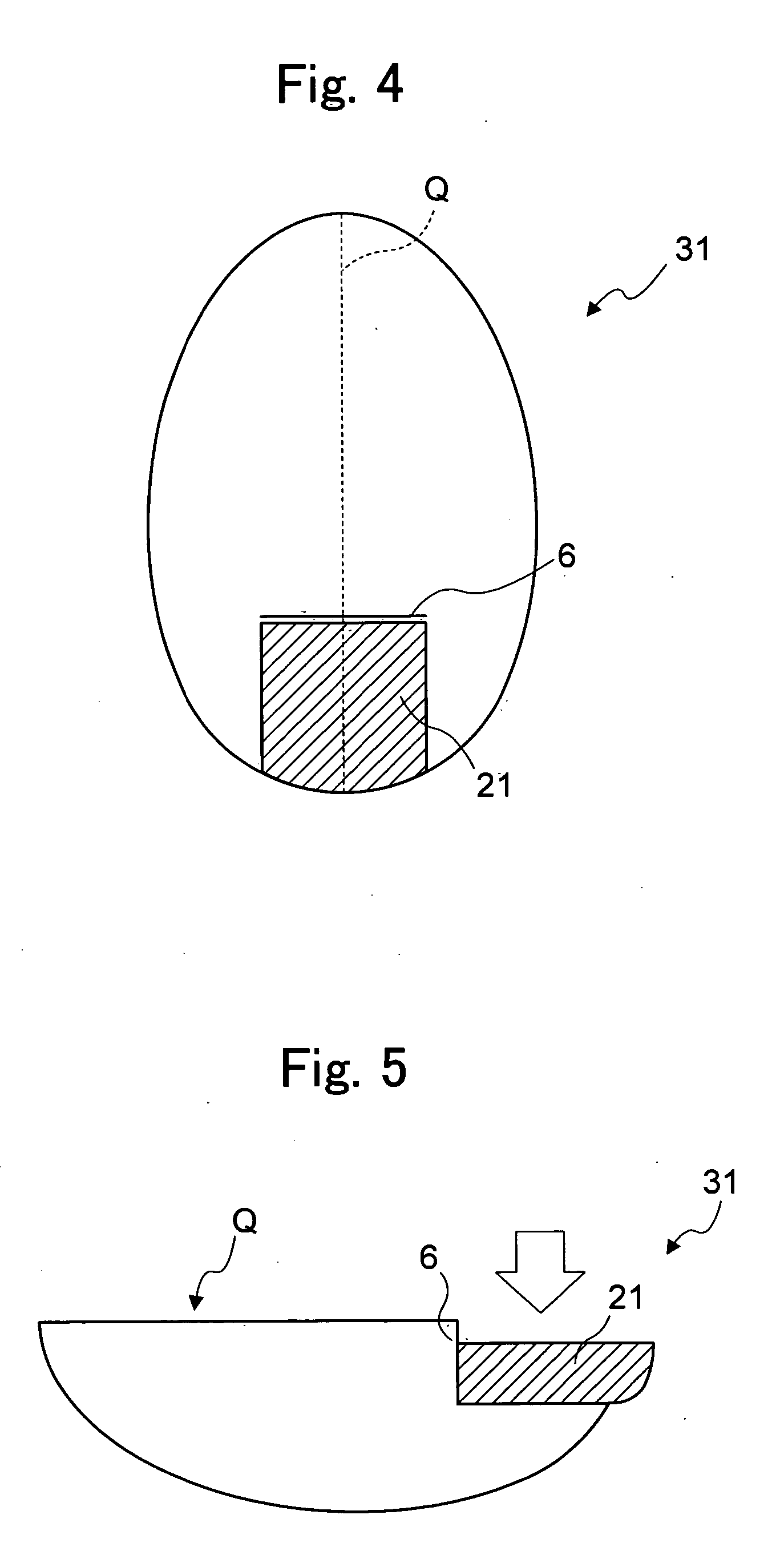
[0092] An interlabial pad relating to Embodiment 2 will now be explained. In Embodiment 2, as the “rear portion low compression rigidity structure”, an embossment 7 is provided with the absorbent body 32. In Embodiment 2, by providing an embossment 7, with the embossment area given high rigidity, as a trigger for the embossment area to bend, it is possible to arrange that the rear portion of the pad only compresses first.
Rear Portion Low Compression Rigidity Structure
[0093]FIG. 7 is a plan view of an absorbent body 32 of an interlabial pad related to Embodiment 2. In Embodiment 2, the embossment 7 is arranged in a discontinuous row in a direction perpendicular to the direction of the central axis Q. Furthermore, to explain the behavior of the embossment 7 in Embodiment 2, FIG. 8 is a side view with compression force applied in a vertical direction to the absorbent body 32 that is folded in two.
[0094] As shown in FIG. 7, the embossment 7 is implemented discontinuously in an area ...
modified example of embodiment 2
[0098]FIG. 9 is a plan view of an absorbent body 33 of an interlabial pad related to a modified example of Embodiment 2. In the absorbent body 33 shown in FIG. 9, embossments 71 are disposed adjacently and discontinuously, at intervals, in an area extending more towards the front than the center point of the central axis Q. In the pad using this type of absorbent body 33, the rigidity of the low compression rigidity portion 23, the portion that makes contact more to the rear than the posterior labial commissure when worn, is lower than the rigidity of the portion that fits the vestibule floor so that the rear portion of the pad is compressed easily, and can bend easily in a direction away from the body, first.
PUM
Abstract
An interlabial pad fits a vaginal opening and a vestibule floor without a gap with the vaginal opening or the vestibule floor. The pad prevents leakage of menstrual blood from a gap and prevents dropping out of the pad when the pad is worn between labia. The interlabial pad is provided with an absorbent body for absorbing and holding body fluid, has a central axis, and is worn with at least one portion held by labia minora, between the labia, so that at least one portion close to the central axis when worn touches the vestibule floor inside the labia of the wearer, and is also provided with a rear portion low compression rigidity structure, so that a rear portion that is positioned to the rear of the wearer and, when worn, touches the body of the wearer first, has low compression rigidity in comparison to a front portion positioned to the front.
Description
[0001] This application is based on and claims the benefit of priority from Japanese Patent Application No. 2005-061645, filed on 4 Mar. 2005, the content of which is incorporated herein by reference. BACKGROUND OF THE INVENTION [0002] 1. Field of the Invention [0003] The present invention relates to an interlabial pad that can be made to fit a vaginal opening and a vestibule floor without a gap with the vaginal opening or the vestibule floor occurring, the pad enabling leakage of menstrual blood from a gap to be prevented, and dropping out of the pad to be avoided, when a wearer wears the pad between labia. [0004] 2. Related Art [0005] Conventionally, sanitary napkins or tampons are generally used as sanitary products for women. With regard to the sanitary napkins, considerable efforts have been made to prevent leakage of menstrual blood from a gap that occurs due to poor contact with the vicinity of the vaginal opening. Moreover, in the case of tampons, due to product attributes t...
Claims
Application Information
Patent Timeline
Application Date:The date an application was filed.
Publication Date:The date a patent or application was officially published.
First Publication Date:The earliest publication date of a patent with the same application number.
Issue Date:Publication date of the patent grant document.
PCT Entry Date:The Entry date of PCT National Phase.
Estimated Expiry Date:The statutory expiry date of a patent right according to the Patent Law, and it is the longest term of protection that the patent right can achieve without the termination of the patent right due to other reasons(Term extension factor has been taken into account ).
Invalid Date:Actual expiry date is based on effective date or publication date of legal transaction data of invalid patent.

