Corrugated pipe with outer layer

a corrugated pipe and outer layer technology, applied in the direction of coatings, mechanical devices, other domestic objects, etc., can solve the problems of pipe failure, pipe wall thickening, pipe use, etc., and achieve the effect of improving the resistance to deformation

a corrugated pipe and outer layer technology, applied in the direction of coatings, mechanical devices, other domestic objects, etc., can solve the problems of pipe failure, pipe wall thickening, pipe use, etc., and achieve the effect of improving the resistance to deformation

US20060201567A1Active Publication Date: 2006-09-14ADVANCED DRAINAGE SYST

Image

  • Corrugated pipe with outer layer
  • Corrugated pipe with outer layer
  • Corrugated pipe with outer layer

Examples


Embodiment Construction

[0025] Reference will now be made in detail to the presently preferred embodiments of the invention, examples of which are illustrated in the accompanying drawings.

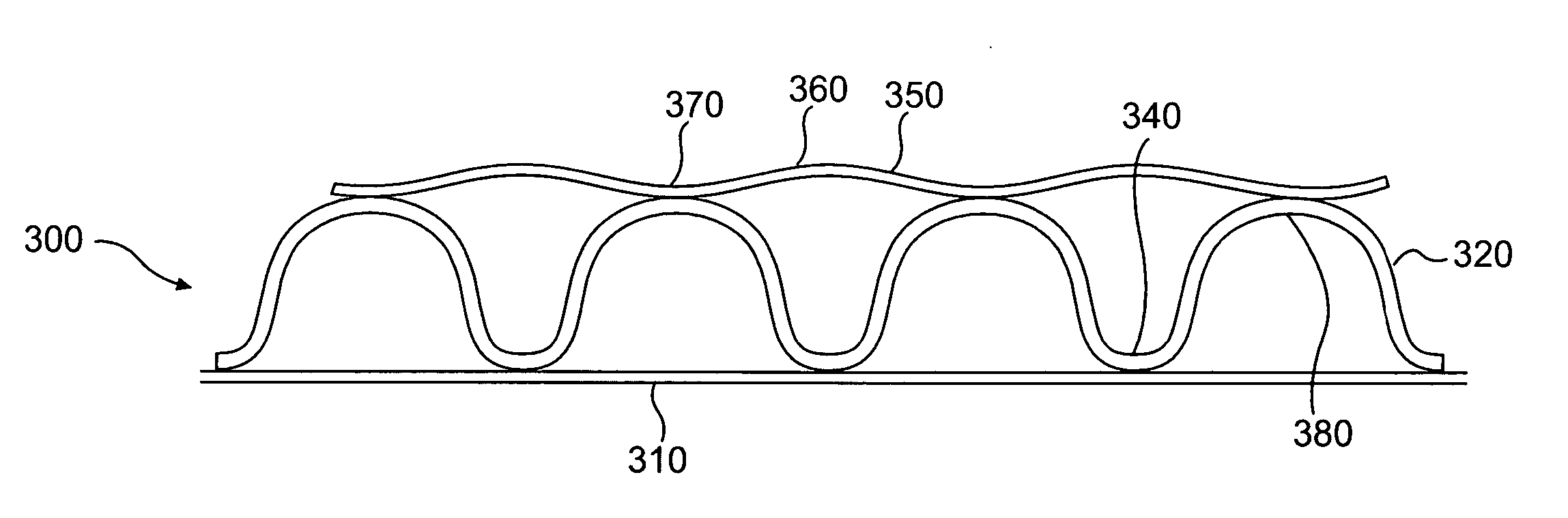
[0026]FIG. 3 illustrates a cross section of a sidewall of an examplary embodiment of the present invention. The section of pipe wall 300 preferably includes a smooth inner wall 310 and a corrugated outer wall 320. The inner wall 310 has a smooth interior surface to improve hydraulics. The corrugated outer wall 320 provides a high strength-to-weight ratio.

[0027] The corrugated outer wall 320 includes corrugation crests 330 and corrugation valleys 340. On top of the corrugated outer wall 320 is an outer layer 350 of the pipe wall 300 that includes convex sections 360 and concave sections 370. The concave sections 370 of the outer layer 350 are generally aligned with the crests 330 of the corrugations. The convex sections 360 extend outwardly between adjacent crests 330 of the outer wall 320.

[0028] Two exemplary dimension...


PUM

PropertyMeasurementUnit
thicknessaaaaaaaaaa
thicknessaaaaaaaaaa
thicknessaaaaaaaaaa

Abstract

A pipe having an axially extending bore is defined by a pipe wall including a corrugated outer wall having axially adjacent annular outwardly-extending crests separated by valleys. The pipe wall also includes a non-linear outer layer having adjacent concave portions and convex portions. The concave portions are aligned with the corrugation crests of the outer wall so that the convex portion of the outer layer extends outwardly between at least two corrugation crests to provide improved resistance to deformation.

Description

TECHNICAL FIELD [0001] This invention relates generally to corrugated pipe having an additional outer layer, and more particularly, to such a corrugated pipe for use in the drainage of soil and transportation of surface water by gravity. BACKGROUND [0002] Corrugated pipe that is commonly used for drainage of soil and transportation of surface water typically has a profile with sides of the corrugation that are fairly steep and a top or crest of the corrugation that is fairly flat. [0003] There are two basic ways that pipe can fail in use: by deforming excessively or by fracturing. Stiffer material is less likely to deform but more likely to fracture under stress. Flexible material is more likely to deform but less likely to fracture under stress. Deformation is expressed as a ratio of elongation of the material to its original material length and is called “strain.” Stress causes the deformation that produces strain. The modulus, or stiffness, of a plastic is the ratio of stress div...

Claims


Application Information

Patent Timeline
14 Sep 2006
Publication
US20060201567A1
IPC
F16L57/00; B29C48/09; B29C48/151; B29C48/21
CPC
B29C47/0023; B29C47/005; B29C47/021; B29C47/065; B29L2009/00; B29L2016/00; B29L2023/003; F16L9/00
Inventors
GODDARD, JAMES B.; KURDZIEL, JOHN MARTIN