Motorcycle exhaust system

a technology for exhaust systems and motorcycles, applied in the direction of cycles, machines/engines, cycle equipment, etc., can solve the problem that the muffler generally cannot be further lowered

Active Publication Date: 2006-09-14
YAMAHA MOTOR CO LTD
View PDF41 Cites 31 Cited by
  • Summary
  • Abstract
  • Description
  • Claims
  • Application Information

AI Technical Summary

Problems solved by technology

The muffler generally cannot be further lowered due to the desire for maintaining sufficient minimum road clearance.

Method used


Image

  • Motorcycle exhaust system
  • Motorcycle exhaust system
  • Motorcycle exhaust system

Examples


Embodiment Construction

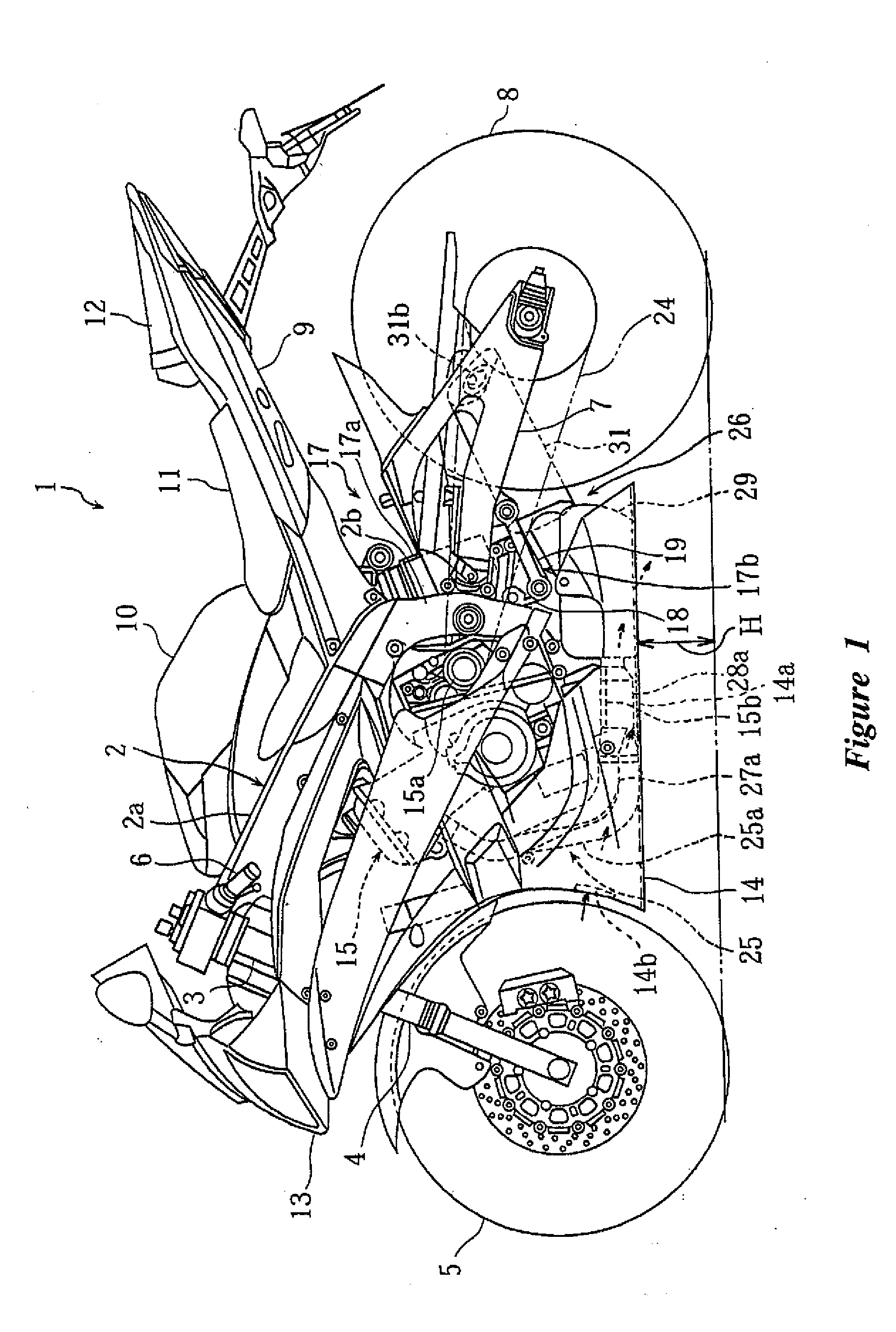
[0029] With reference now to FIGS. 1 through 12, an exhaust system is shown that is arranged and configured in accordance with certain features, aspects and advantages of the present invention. In the following description, the front-to-rear and right-to-left directions refer to the front-to-rear and right-to-left directions as viewed from a rider sitting on a seat.

[0030] In the figures, a motorcycle 1 generally comprises a front fork 4 that is supported by a head pipe 3 such that the front fork 4 can be steered to the left and right directions. The head pipe 3 is attached to the front end of a vehicle body frame 2. The vehicle body frame can be made of an aluminum alloy or any other suitable material. A front wheel 5 and steering handlebars 6 are disposed at the lower end and the upper end of the front fork 4, respectively. Left and right rear brackets 2b of the vehicle body frame 2 support a rear arm 7 such that the rear arm 7 can pivot upward and downward. A rear wheel 8 is disp...


PUM


Abstract

A motorcycle has an exhaust system configured to extend below the engine while providing a sufficient length and a sufficient angle of through which the motorcycle can lean. A muffler unit comprises a first muffler connected with the exhaust pipe unit and disposed between the engine and a rear wheel. The muffler unit also comprises a second muffler that is connected with the first muffler and that is disposed near the side of the rear wheel. The first muffler comprises inclined portions that are formed on the left and right sides of the first muffler when viewed from the front of the vehicle. The second muffler has inclined portions that extend at an angle approximately equal to that of the inclined portions of the first muffler.

Description

RELATED APPLICATIONS [0001] This application claims the priority of Japanese Patent Application No. 2005-316085, filed Oct. 31, 2005, Japanese Patent Application No. 2005-161445, filed Jun. 1, 2005 and Japanese Patent Application No. 2005-069761, filed Mar. 11, 2005, each of which is here by incorporated by reference in its entirety. BACKGROUND OF THE INVENTION [0002] 1. Field of the Invention [0003] The present invention generally relates to motorcycle exhaust systems. More particularly, the present invention relates to a motorcycle exhaust systems that comprise an exhaust pipe unit connected with an engine and a muffler unit connected with the exhaust pipe unit. [0004] 2. Description of the Related Art [0005] In some motorcycles, a muffler is disposed below an engine of the motorcycle to lower the center of gravity of the vehicle as much as possible. Such a placement of the muffler lowers the center of gravity because the muffler typically is a heavy component. JP-A-2002-303133 di...

Claims


Application Information

Patent Timeline
Patent Type & Authority Applications(United States)
IPC IPC(8): F01N7/08F01N7/02B62M7/02F01N1/08F01N3/24F01N13/00F01N13/02F01N13/08F01N99/00
CPCB60Y2200/12B62K19/30F01N1/084F01N1/10F01N1/165F01N1/24F01N3/28F01N13/02F01N13/08F01N13/082F01N13/1805F01N13/1822F01N2230/04F01N2340/04F01N2470/18F01N2490/14F01N2490/155F01N2590/04F01N13/011Y02A50/20
Inventor TERASHIMA, YASUTOTAKESHITA, HIROTOSHI
Owner YAMAHA MOTOR CO LTD
Why Eureka
Try Eureka