Microdispensing pump

a micro-dispensing pump and pump body technology, applied in the direction of instruments, single-unit apparatuses, movable measuring chambers, etc., can solve the problems of high undesired label removal inadvertently or improperly

Inactive Publication Date: 2006-09-14
COHEN
View PDF5 Cites 0 Cited by
  • Summary
  • Abstract
  • Description
  • Claims
  • Application Information

AI Technical Summary

Benefits of technology

[0006] In a second aspect of the subject invention, a pump is provided having an overcap formed to removably mount onto a pump body, the overcap defining an at least liquid-tight seal with the pump body at locations spaced from a nozzle on the pump body. In this manner, the overcap can be used to restrict the introduction of dirt, debris and other contaminants to the nozzle of the pump, with the pump not being in use. As such, the pump can be provided with a sufficiently proper seal which can withstand hazardous conditions, including those rigorous conditions imposed by CCIT (container closure integrity testing).

Problems solved by technology

Particularly with labels having instructions and / or warnings, inadvertent or improper removal of the label is highly undesired.

Method used


Image

  • Microdispensing pump
  • Microdispensing pump
  • Microdispensing pump

Examples


Embodiment Construction

:

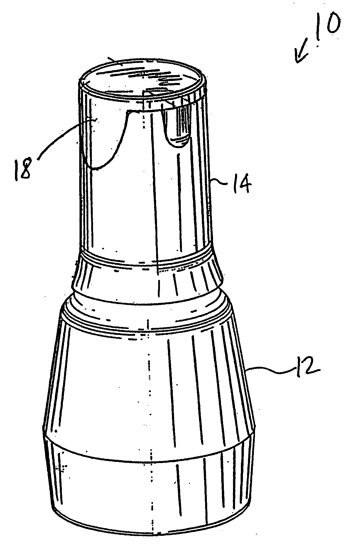
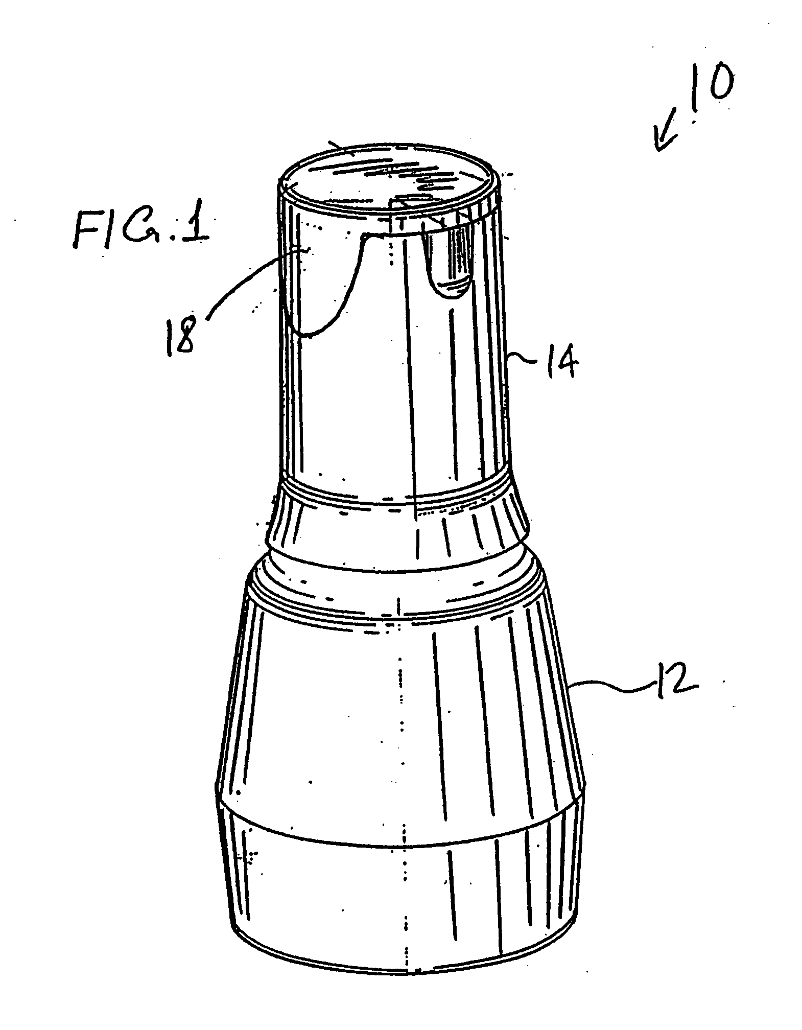
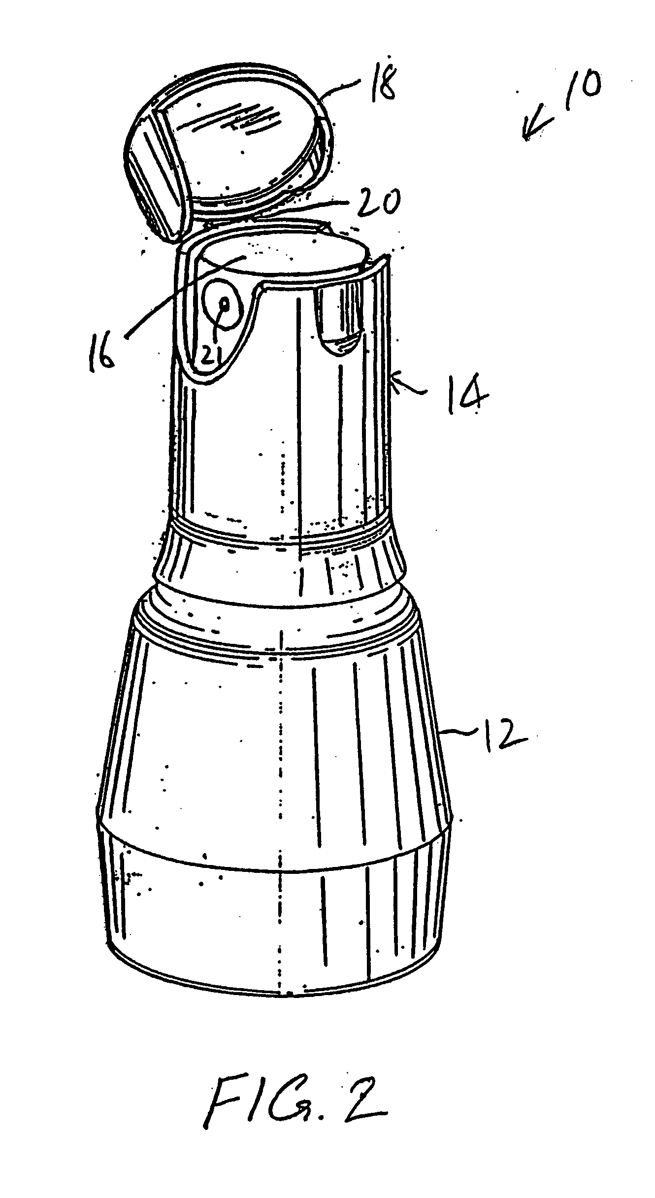
[0018] With reference to FIGS. 1 and 2, a representative pump 10 is depicted, which may include one or more of the aspects of the subject invention. The pump 10 is formed for dispensing fluid, preferably ophthalmic medication. As will be recognized by those skilled in the art, the pump 10 may be formed with any configuration; for illustrative purposes, the pump 10 includes a pump body which may include a handle 12 (which may house a fluid reservoir), a neck portion 14, a dispensing cap 16 disposed within the neck portion 14, and a flip cap 18 hingedly mounted to the neck portion 14 via a hinge 20. A nozzle 21 is formed in the dispensing cap 16 to dispense the fluid upon actuation of the pump; the actuation preferably being achieved by depressing the dispensing cap 16 and causing downward travel thereof. The pump 10 is preferably of a lift-pump type formed in accordance with the teachings set forth in U.S. Pat. No. 5,881,956 and U.S. patent application Ser. No. 10 / 123,390, but may a...


PUM


Abstract

Several different features are provided for use with a pump, particularly a microdispensing pump. a first aspect of the subject invention, latch fingers are provided which coact with a stop member to yieldingly inhibit movement of an actuator of the pump to ensure sufficient momentum is provided to the pump for actuation. In a second aspect of the invention, an overcap is provided which defines an at least liquid-tight seal with the pump body at locations spaced from a nozzle of the pump to limit ingress of contaminants into the nozzle. In a third aspect, at least one protruding bead is provided in proximity to at least one edge of a label mounted to the pump body to restrict removal thereof. In a fourth aspect, at least one rib is provided in proximity to a dispensing cap to provide lateral stability thereto.

Description

CROSS-REFERENCE TO RELATED APPLICATION: [0001] This application claims priority of U.S. Provisional Application No. 60 / 323,659, filed Sep. 20, 2001.BACKGROUND OF THE INVENTION [0002] Microdispensing pumps are known in the prior art, such as those disclosed in U.S. Pat. No. 5,881,956; WIPO PCT Published Application No. WO 01 / 14245; and related applications. The entire disclosures of these references are incorporated by reference herein. [0003] Although microdispensing pumps are known in the prior art, problems still exist with their operation and storage. For example, with a microdispensing pump used in an ophthalmic application, ingress of dirt into the pump's nozzle is a major concern. With prior art eye dropper bottle designs, a threaded overcap is typically provided which is formed to sufficiently thread onto a dropper bottle body to press against and form a tight mechanical seal against the dispensing aperture of the dropper bottle. However, with a microdispensing pump, such a d...

Claims


Application Information

Patent Timeline
Patent Type & Authority Applications(United States)
IPC IPC(8): G01F11/10B05B11/00B67D7/60
CPCB05B11/0027B05B11/3001B05B11/3023B05B11/3052B05B11/3054B05B11/3059B05B11/1001B05B11/1023B05B11/1054B05B11/1052B05B11/1059
Inventor COHENKELLY, NIGEL
Owner COHEN
Why Eureka
Try Eureka