Injection hole plate and fuel injection apparatus having the same
- Summary
- Abstract
- Description
- Claims
- Application Information
AI Technical Summary
Problems solved by technology
Method used
Image
Examples
first embodiment
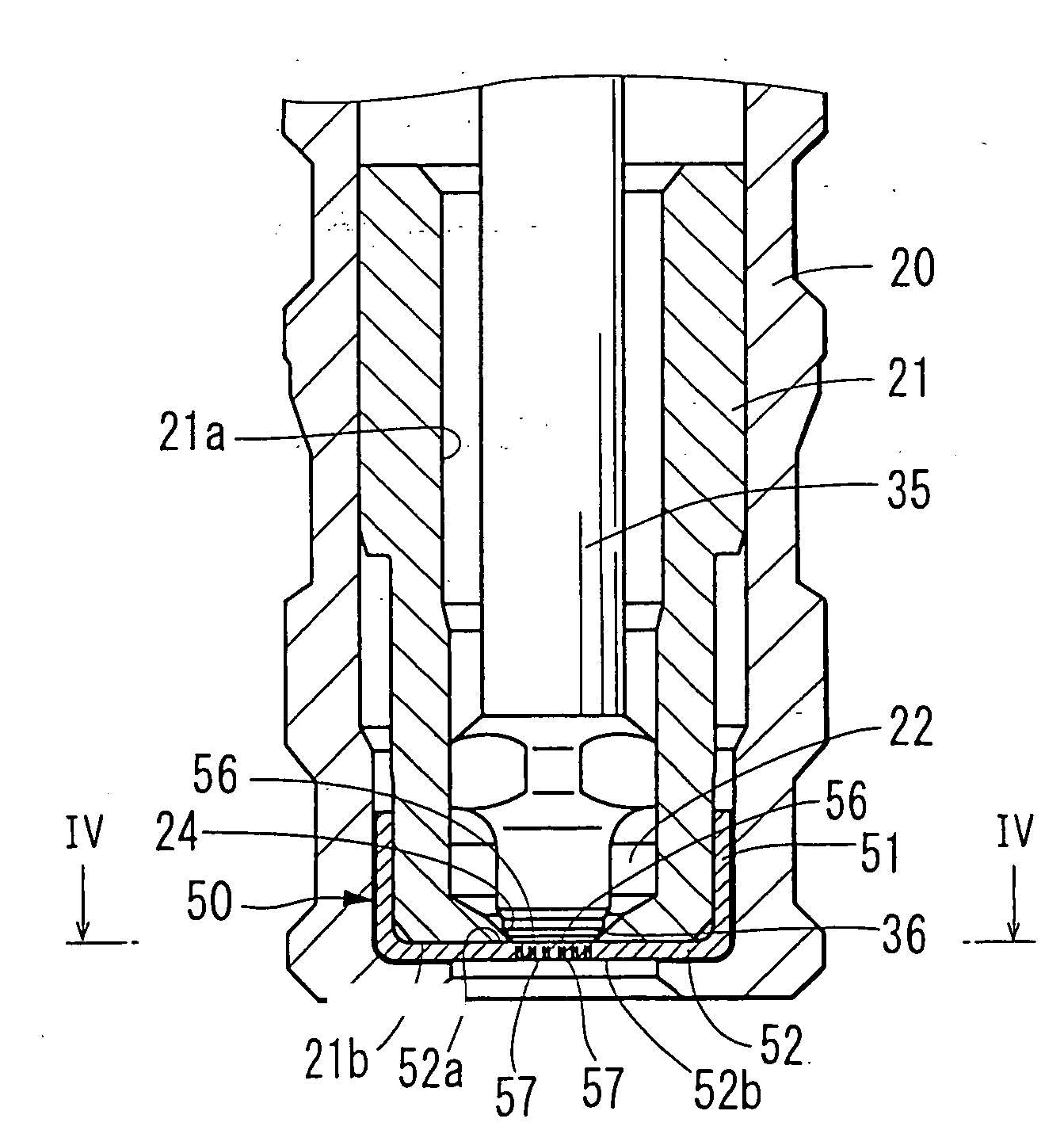
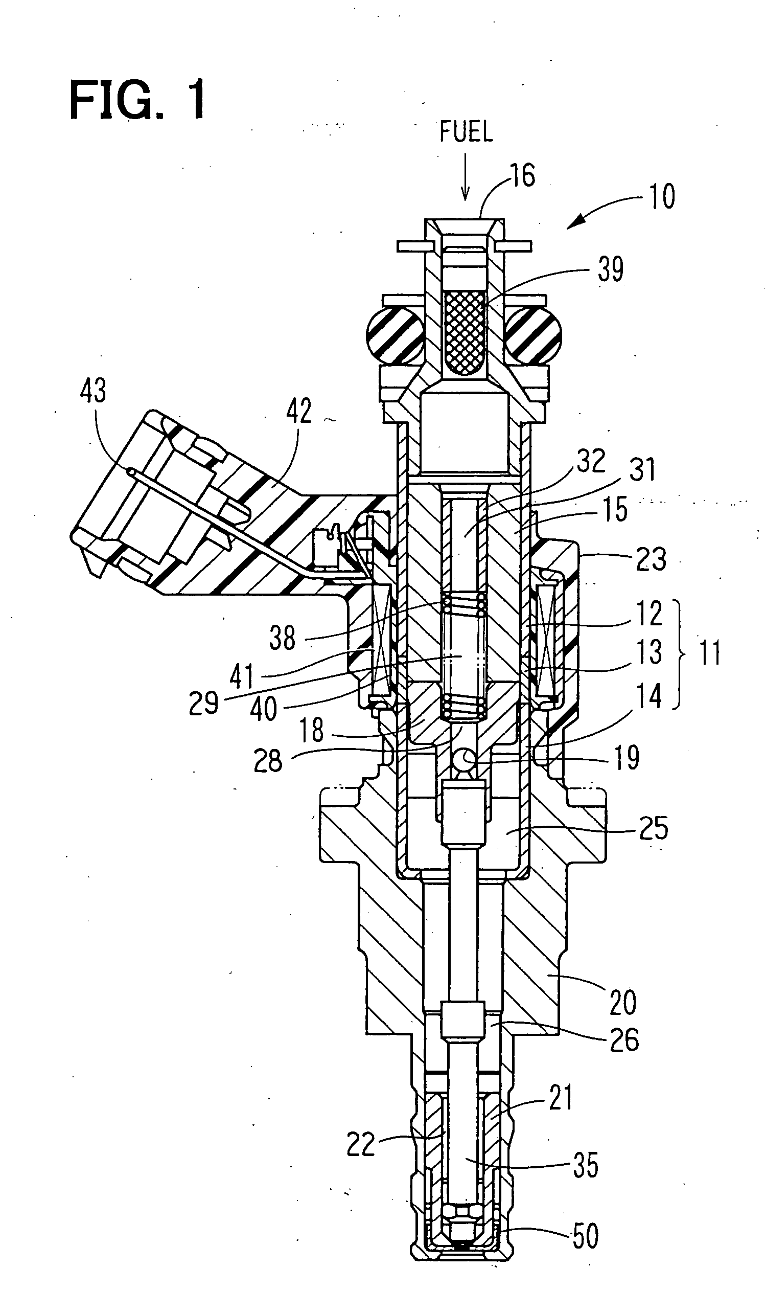
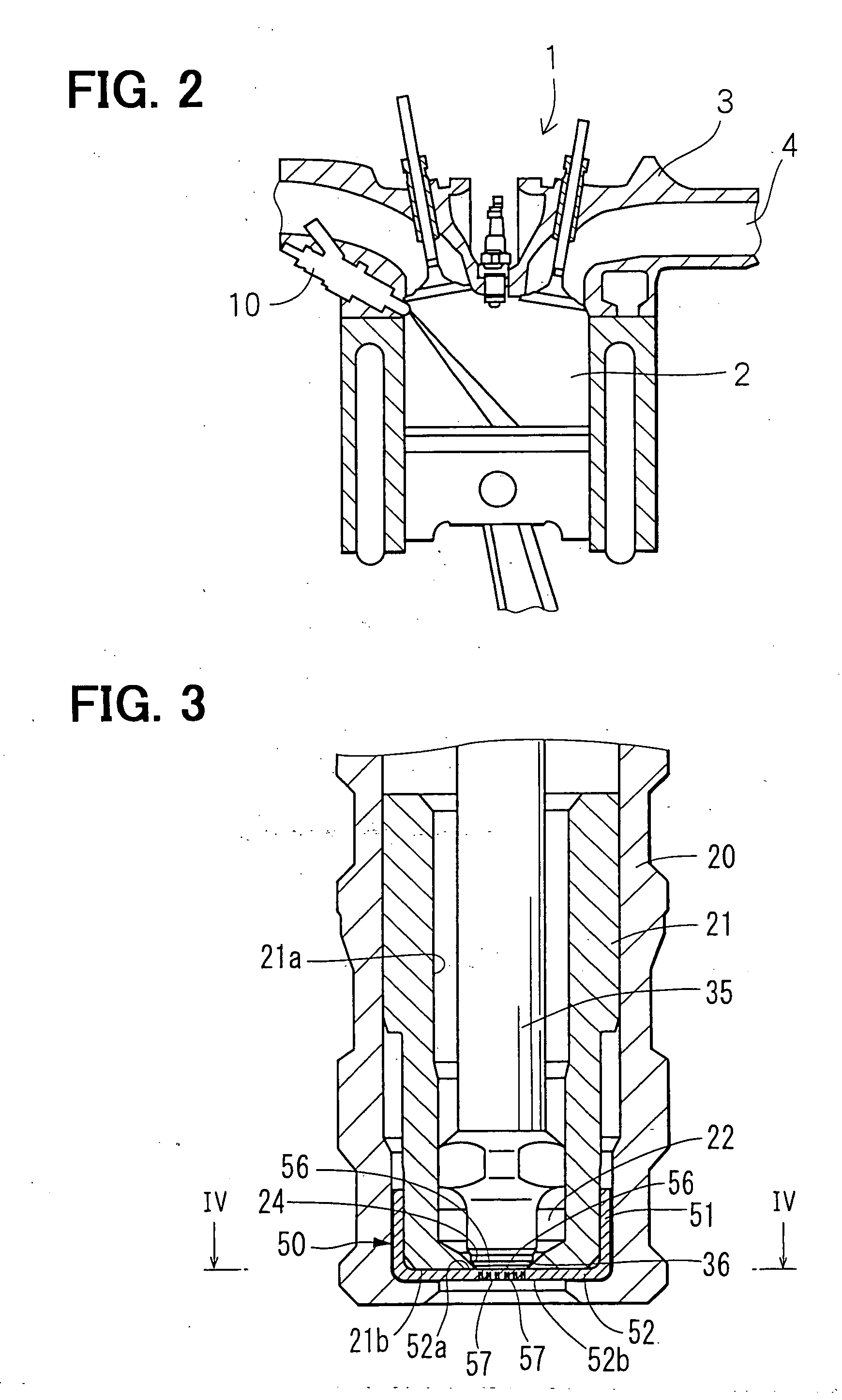
[0051]FIG. 1 shows a fuel injection apparatus (hereinafter, referred to as injector) 10 according to a first embodiment of the present invention. As shown in FIG. 2, the injector 10 is installed to a cylinder head 3, which forms combustion chambers (only one is depicted) 2 of a gasoline engine 1. That is, the injector 10 is used in the gasoline engine 1 of a direct injection type, in which fuel is directly injected into each combustion chamber 2. However, it should be understood that the injector 10 is equally applicable to a gasoline engine of a premixed combustion type, in which fuel is injected into intake air that flows through an intake pipe 4 communicated with the combustion chamber 2.
[0052] As shown in FIG. 1, a housing 11 is formed into a cylindrical shape. The housing 11 includes a first magnetic portion 12, a non-magnetic portion 13 and a second magnetic portion 14, which are coaxially arranged. The non-magnetic portion 13 prevents magnetic short circuit between the first...
second and third embodiments
[0068]FIG. 10 shows an injection hole plate according to a second embodiment of the present invention, and FIG. 11 shows an injection hole plate according to a third embodiment of the present invention. Components similar to those of the first embodiment will be indicated by the same numerals.
[0069] With reference to FIG. 10, in an injector 100 of the second embodiment, an extending direction of each first-side hole section 58 associated with the corresponding second-side hole section 54 is set such that a swirl direction of one of each adjacent two second-side hole sections 54 is opposite to a swirl direction of the other one of each adjacent two second-side hole sections 54, as indicated by arrows in FIG. 10. With reference to FIG. 11, in an injector 150 of the third embodiment, the second-side hole section 54 of each injection hole 57 is positioned in a corresponding one of vertexes of an imaginary regular hexagonal plane tessellation, which is made of a plurality of regular hex...
fourth embodiment
[0071]FIGS. 13 and 14A-14C show an injection hole plate of an injector according to a fourth embodiment of the present invention. Components similar to those of the first embodiment will be indicated by the same numerals.
[0072] The injection hole plate 50 of the injector 200 of the fourth embodiment includes two members, i.e., first and second members 220, 230, which are joined together in the base wall portion 52 of the injection hole plate 50. The first member 220 forms a portion of the injection hole plate 50, which constitutes the downstream end 52b of the base wall portion 52. The second member 230 forms another portion of the injection hole plate 50, which constitutes the upstream end 52a of the base wall portion 52. The second member 230 further forms the peripheral wall portion 51 of the injection hole plate 50.
[0073] The first member 220 includes the second-side hole sections 54 and downstream side portions (second-side hole section side portions) 222 of the first-side ho...
PUM
 Abstract
Description
Claims
Application Information
 - R&D
- Intellectual Property
- Life Sciences
- Materials
- Tech Scout
- Unparalleled Data Quality
- Higher Quality Content
- 60% Fewer Hallucinations
Browse by: Latest US Patents, China's latest patents, Technical Efficacy Thesaurus, Application Domain, Technology Topic, Popular Technical Reports.
© 2025 PatSnap. All rights reserved.Legal|Privacy policy|Modern Slavery Act Transparency Statement|Sitemap|About US| Contact US: help@patsnap.com


