Systems for three-dimensional viewing and projection

a three-dimensional and projection technology, applied in the field of three-dimensional projection systems, can solve the problems of poor adaptability of lenticular systems to viewing systems such as computer displays and televisions, poor quality of lenticular systems, and inconvenient use of viewing apparatuses

Inactive Publication Date: 2006-09-14
TAMIRAS PER PTE LTD LLC
View PDF37 Cites 90 Cited by
  • Summary
  • Abstract
  • Description
  • Claims
  • Application Information

AI Technical Summary

Benefits of technology

[0101] The present invention successfully addresses the shortcomings of the presently known configurations by providing a flatscreen fullcolor directly displayed or projected stereoscopic vision without eyeglasses or other optical means engaged close to the eyes of the viewer. Furthermore, some of the systems for three-dimensional viewing according to the present invention do not restrict the viewer to specific position and distance relative to the display, which viewer is thus free...

Problems solved by technology

As far as the first category is of concern, viewing apparatuses of the sort which require lenses, prisms, or mirrors held in proximity with the viewer's eyes, are generally less convenient than alternatives which do not require special eyeware and do not require the viewer using them to hold the apparatus or to approach his eyes to special eyepieces.
As far as the second category is of concern, lenticular systems are relatively difficult and expensive to manufacture for high quality image presentation due to the amount of precision associated with their production, if high-resolution images are desired.
Evidently, lenticular systems are not well adapted for viewing systems such as computer displays and television and are therefore not in wide use.
As mentioned, systems falling into these categories share a common disadvantage, they all require an inherent use of special eyeglasses or a headgear.
The necessity for optical apparatus held near the eyes subtracts from the pleasure, comfort and naturalness of the experience of viewing the display, and may, depending on the system used, add significantly to the expense.
These and similar systems have the disadvantage of requiring use of polarizing eyeglasses.
Certain further disadvantages characterize systems which use polarizing glasses yet do not use switching means (c.f., fifth category).
An inherent disadvantage associated with such schemes is that part of the display surface is blocked from the view of each eye.
On the other hand, systems aimed at ensuring that all areas of the display space will be used in representing each of the left and right images (sequentially if not simultaneously) tend to be somewhat complex and are potentially relatively expensive to manufacture.
U.S. Pat. No. 5,083,851 to MacDonald provides an example of a system with undoubted qualities but which might be expensive to implement.
Yet, this projection system has the disadvantages of (i) requiring the viewer to wear eyeglasses, and (ii) requiring special projection devices which involve two projectors (or a specially designed single projector having ...

Method used


Image

  • Systems for three-dimensional viewing and projection
  • Systems for three-dimensional viewing and projection
  • Systems for three-dimensional viewing and projection

Examples


first embodiment

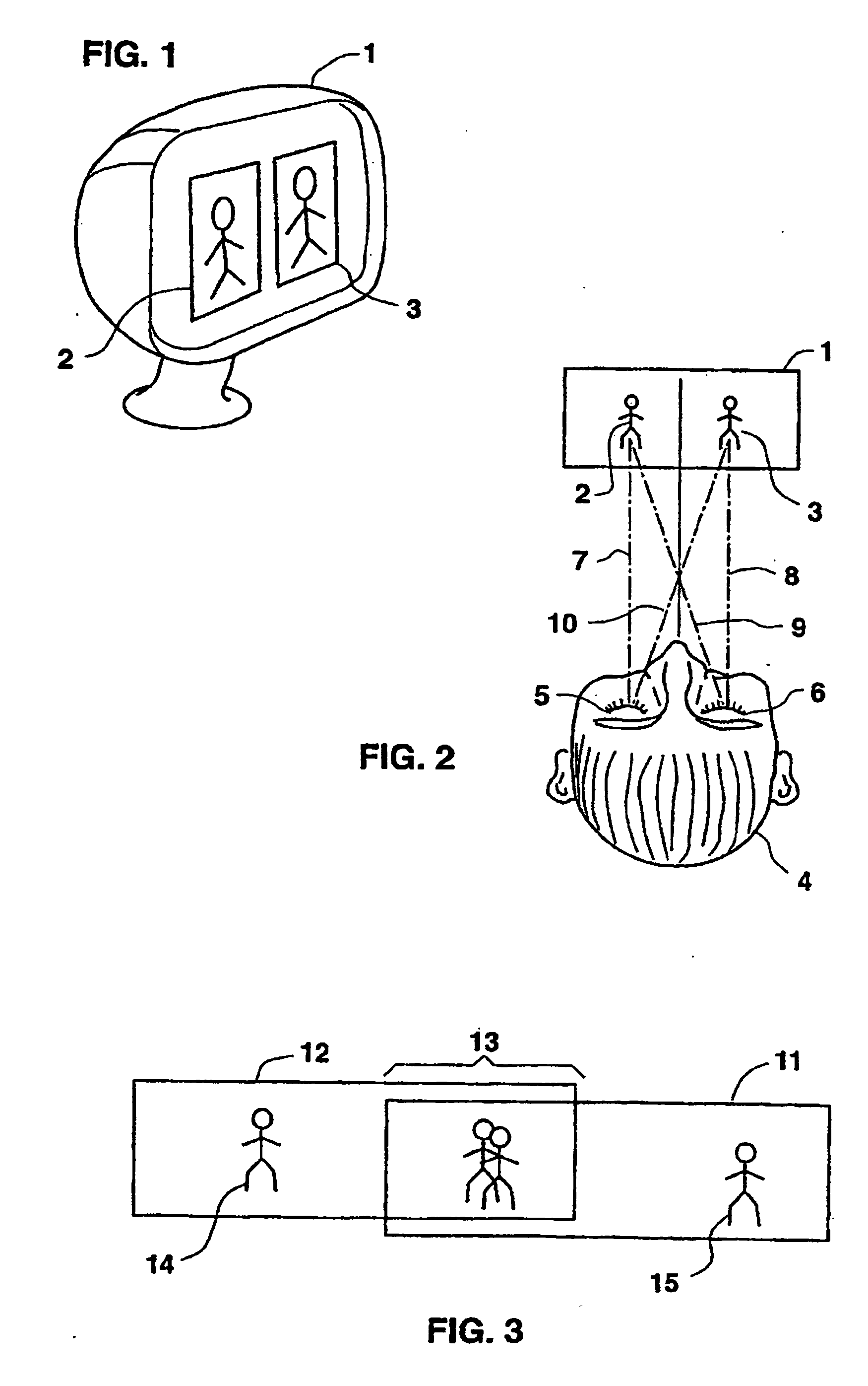
[0153] The method of viewing a 3D-image according to the present invention is illustrated in FIG. 2.

[0154] First, FIG. 2 shall be used to review the way a viewer 4 normally looks at an object. Viewer 4, when looking at an ordinary object, for example left image 2, in an ordinary manner, directs both his left eye 5 and his right eye 6 to image 2, resulting in line of sight 7 for left eye 5 and line of sight 9 for right eye 6. Similarly, when viewer 4 normally looks at image 3 the viewer directs both eyes 5 and 6 to that object, invoking lines of sight 10 for left eye 5 and 8 for right eye 6.

[0155] If image 2 is a left image as defined, and image 3 a right image, then a stereoscopic binocular (i.e., three-dimensional) view can be obtained by viewer 4 who diverges his eyes in such a way that left eye 5 is directed towards left image 2, resulting in line-of-sight 7, while at the same time right eye 6 is directed towards right image 3 resulting in line-of-sight 8.

[0156] Left 2 and righ...

second embodiment

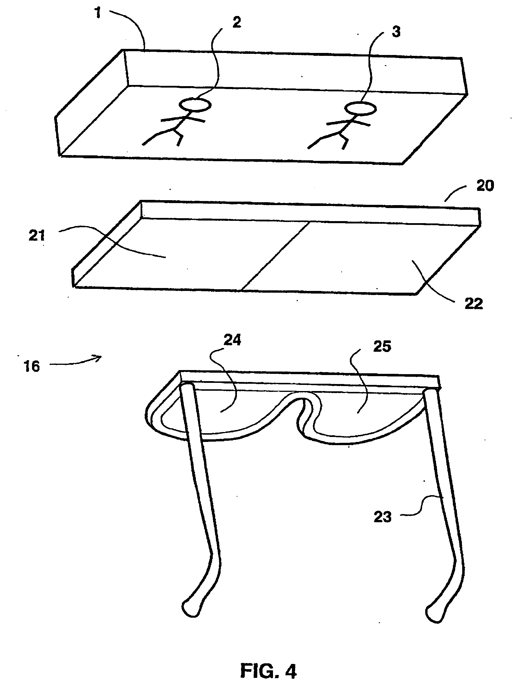
[0168] With reference now to FIG. 4, presented is the present invention, aimed at solving the problem of flanking (i.e., peripheral) images as described above. FIG. 4 shows a system 16 for three-dimensional viewing. System 16 includes a layer 20, layer 20 includes light polarizing means and is divided into a first area 21 and a second area 22, area 21 substantially covering left image 2, whereas area 22 substantially covering right image 3, both images displayed on display 1. It should be noted that in intent, layer 20 is close to display 1, yet it has been moved disproportionally far away in the drawing for clarity in showing the placement of images on display 1. Area 21 polarizes light in a first orientation, whereas area 22 polarizes light in a second orientation, which is substantially perpendicular to the first. The viewer then wears polarizing eyeglasses 23 whose left eyepiece 24 allows only light polarized in the first orientation to enter the left eye, and whose right eyepie...

third embodiment

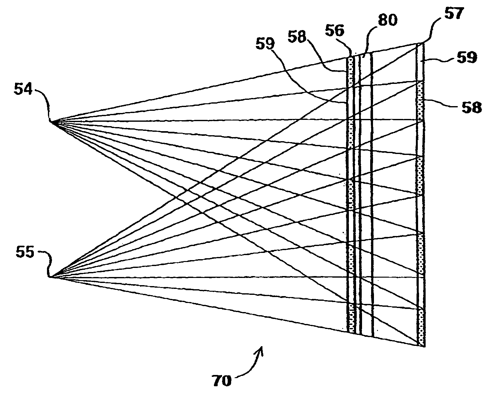
[0172] With reference now to FIG. 5, presented is the present invention. According to the third embodiment provided is another system 35 for three-dimensional viewing, system 35 enables to use images which are not limited in width, and which do not require special divergence or convergence of the eyes for them to be three-dimensionally viewed.

[0173] As mentioned above, U.S. Pat. No. 5,050,961 to Venolia discloses a system which supplies appropriate subregions of left and right images to the appropriate eyes, yet leaves 50% of the display area unseen by each of the eyes, thus affecting the quality (i.e., resolution) of the perceived 3D-image. On the other extreme, U.S. Pat. No. 5,083,851 to MacDonald provides means for using all image information of the display area for both left and right images, yet MacDonald means is relatively expensive and complex compared to the system 35 presented in FIG. 5 and described hereinbelow.

[0174] System 35 includes a display 1, a light polarizing la...


PUM


Abstract

Systems for three-dimensional viewing and projection aimed at full-color flat-screen binocular stereoscopic viewing without the use of eyeglasses for the viewer. According to the invention, light emanating from a display or projected thereat presenting a left image and a right image is directed only to the appropriate left or right eyes of at least one viewer using various combinations of light polarizing layers and layers of light rotating means.

Description

RELATED APPLICATIONS [0001] This is a continuation of U.S. patent application Ser. No. 09 / 987,793, filed on Nov. 16, 2001, which is a continuation of U.S. patent application Ser. No. 09 / 750,702, filed on Jan. 2, 2001, now abandoned, which is a continuation of U.S. patent application Ser. No. 09 / 101,984, filed on Jul. 21, 1998, now U.S. Pat. No. 6,252,707, which is a National Phase of PCT Patent Application No. PCT / US97 / 00778, filed on Jan. 21, 1997, which is a continuation of U.S. patent application Ser. No. 08 / 657,227, filed on Jun. 3, 1996, now U.S. Pat. No. 5,822,117, which is a continuation of U.S. patent application Ser. No. 08 / 589,510, filed on Jan. 22, 1996, now U.S. Pat. No. 5,973,831. PCT Patent Application No. PCT / US97 / 00778, also claims priority from Israel Patent Application No. 119437, filed on Oct. 16, 1996. The contents of the above applications are all incorporated by reference.FIELD AND BACKGROUND OF THE INVENTION [0002] The present invention relates in general to s...

Claims


Application Information

Patent Timeline
IPC IPC(8): G02B27/26G02B30/25G02B30/30G03B35/26H04N13/239H04N13/363H04N13/393H04N13/395
CPCG02B27/2207G02B27/2214G02B27/26G03B35/26H04N13/0239H04N13/0257H04N13/0285H04N13/0296H04N13/0402H04N13/0404H04N13/0409H04N13/0418H04N13/0422H04N13/0425H04N13/0431H04N13/0434H04N13/0436H04N13/0438H04N13/044H04N13/0459H04N13/047H04N13/0472H04N13/0475H04N13/0477H04N13/0481H04N13/0484H04N13/0486H04N13/0493H04N13/0495H04N13/0497H04N2013/0081H04N13/302H04N13/337H04N13/341H04N13/305H04N13/395H04N13/32H04N13/344H04N13/376H04N13/324H04N13/393H04N13/368H04N13/38H04N13/31H04N13/257H04N13/296H04N13/339H04N13/315H04N13/334H04N13/363H04N13/286H04N13/373H04N13/239H04N13/371H04N13/327H04N13/383H04N13/398G02B30/23G02B30/25G02B30/30G02B30/27
Inventor KLEINBERGER, PAULKLEINBERGER, ILAN D.
Owner TAMIRAS PER PTE LTD LLC
Why Eureka
Try Eureka